|
THE SYSTEMS DIAGRAM V. Ryan © 2001-10
|
|||
| PDF FILE - CLICK HERE FOR PRINTABLE SYSTEMS DIAGRAM TEMPLATE | |||
| PDF FILE - CLICK HERE FOR INTRODUCTORY SYSTEMS DIAGRAM EXERCISE | |||
When planning a project a ‘systems’ diagram is essential. This will allow you to show your thinking regarding your idea(s) and whether or not they will answer the design problem. It also allows you to think systematically and logically about the design problem and how it can be solved. Above all, it keeps you ‘on track’ and does not allow you to wander too far away from the original design problem. A systems diagram is similar to a flow chart although on first sight it is much simpler and more precise. The diagram is usually part of either, the ideas or development sections. However, do not restrict yourself to these two areas, if you feel it is necessary, use this type of diagram wherever you like in the design process. |
|||
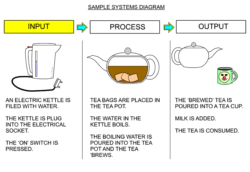
| A simple systems diagram is seen below. This describes making a cup of tea, from the filling an electric kettle, brewing the tea, to pouring the tea into a cup. Remember, almost every process can be divided into INPUT, PROCESS and OUTPUT. When learning about systems diagrams and how they can be used, it is a good idea to practice drawing them, by describing a simple process, such as making a cup of tea. | |||
 |
|||
| CLICK HERE FOR INTRODUCTION TO 'OPEN' AND 'CLOSED' SYSTEM DIAGRAMS | |||
| (Please note: Although the example system diagrams shown below include electronics, system diagrams can be drawn for non-electronic projects/products, as well). | |||
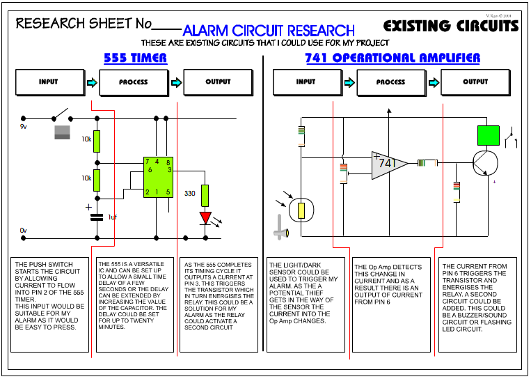
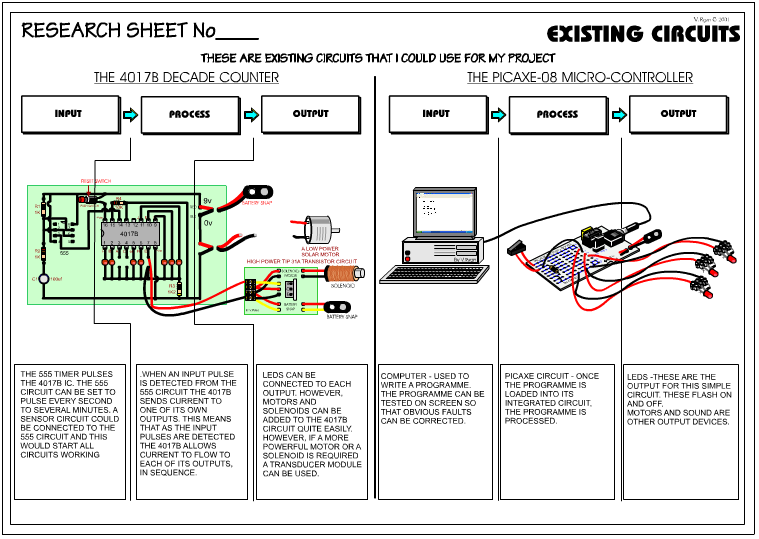
| SYSTEMS DIAGRAM Below is an example of a systems diagram, for an alarm project. The alarm system is for a briefcase, when the case is opened by anyone other than the owner, the alarm sounds. |
|||
 |
|||
|
|||
| HOW TO PRESENT A SYSTEMS DIAGRAM | |||
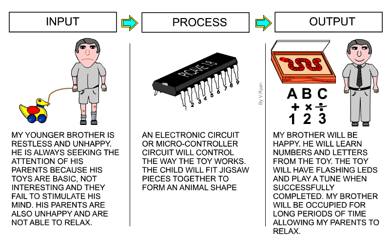
| The systems diagram shown below, shows the inputs,
process and outputs for an education toy designed by a pupil. 1. The systems diagram is divided into three areas - input, process and output. 2. You should write about all the problems you are trying to solve in the INPUT area of the page. Look back to your design problem and write a summary under a simple diagram / picture that reflects all inputs. The example shows an unhappy child with a toy that does not occupy his time productively. 3. The writing under the input drawing should be precise and to the point. There is no need for incredible detail. Include a limited number of inputs, expressed as simple statements. 4. In the PROCESS area describe the type of electronics and / or mechanisms that you intend to use in your project. Keep the descriptions of circuits and mechanisms generalised. Explain how the circuits / mechanisms control the way your product will work. The person using your product may also be part of the PROCESS. In the example, a child fits the pieces of a jigsaw together. Include a simple drawing above the writing. 5. Explain in the OUTPUT area what you think will be the overall outcomes of your product. The example opposite explains that the outcomes of a design for an educational toy will be: The child is happy, His time is occupied productively, He is learning numbers and letters etc....... Include a simple drawing, representing the OUTPUTS above the writing. 7. Always include a simple ‘systems diagram’ above the explanation. This type of diagram is seem often in examinations. |
|||
 |
|||