| CLICK HERE FOR INDEX PAGE | |
THIRD ANGLE ORTHOGRAPHIC DRAWING AN EXAMPLE (WORKING DRAWINGS) |
|
| V. Ryan © 2008 - 2017 | |
| PDF FILE - CLICK HERE FOR PRINTABLE WORKING DRAWING TEMPLATE | |
| YouTube Video - Orthographic Drawing - Lesson 2 | |
 |
|
|
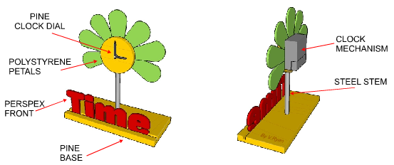
A simple design for a clock is seen below. The design
is based on a flower and consequently the clock dial has petals
surrounding it. It has been drawn in three dimensions using CAD (Computer
Aided design) software. This is one way is which a design can be
presented. |
|
 |
|
|
The animation below shows how a three dimensional drawing can be arranged to present the three important views seen in third angle orthographic drawing. These views, known as elevations are the Front Elevation, Side Elevation and Plan elevation. |
|
 |
|
|
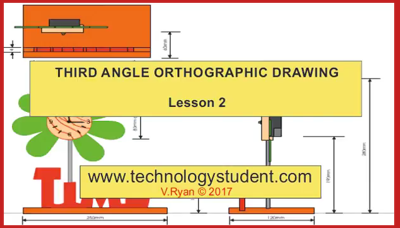
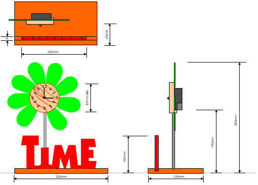
The clock is drawn below, this time in orthographic projection (Third Angle Projection). Three views have been drawn and they are the front, side and plan elevations. This style of accurate drawing is needed when the item is to be manufactured. |
|
| PDF FILE - CLICK HERE FOR PRINTABLE ORTHOGRAPHIC DRAWING EXERCISE | |
 |
|
|
Dimensions (measurements) are then added to the three elevations. This means that overall sizes can be seen. Working drawings usually have a minimum of six dimensions although normally more are required. A drawing of this type is always drawn either to the full size of to a scale. This means that any dimensions that have not been included can be measured directly from the paper. |
|
 |
|
|
|
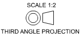
When looking at an orthographic drawing it is very
important to establish the ‘angle of projection’. The most popular system
is third angle projection, as seen on this page. Another system is first
angle projection (dealt with earlier). The symbol identifying third angle
projection is seen opposite. This should be placed on every third angle
projection orthographic drawing so that the person using the drawing
understands immediately the system being applied. |
|
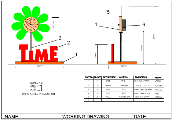
This amended working drawing (below) has only two
elevations of the clock. A plan elevation was not required because the
front and side elevations have enough detail and information to make it
possible to manufacture the clock. |
|
 |
|
|
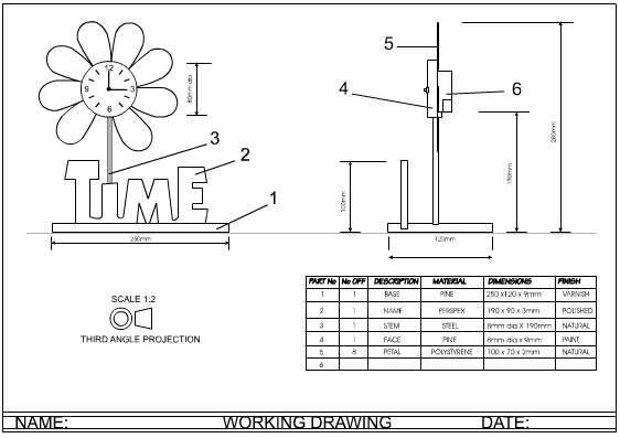
Working drawings are normally presented in a very
formal manner. This means that colour and shade are not used. Outline
drawings are the usual mode of presentation. Colour can hide or mask
detail. |
|
 |
|
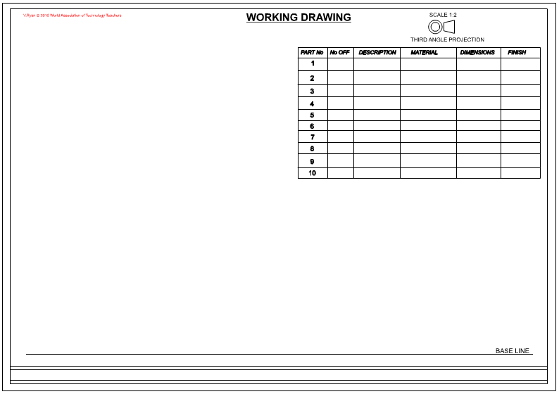
| SAMPLE LAYOUT TO A WORKING DRAWING | |
 |
|
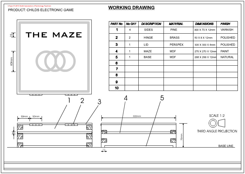
| EXAMPLE WORKING DRAWING AND PARTS LIST | |
 |
|
| CLICK HERE FOR FURTHER DETAILED INFORMATION - WORKING DRAWINGS | |
| CLICK HERE FOR GRAPHICS INDEX PAGE | |
| CLICK HERE FOR DESIGN PROCESS INDEX PAGE | |