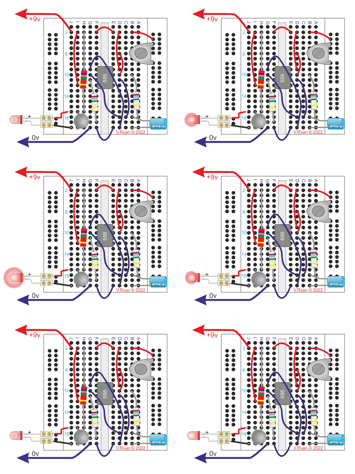
One
555 IC
270 ohm resistor from +9v to the collector of the NPN transistor.
Two 1K resistors
One NPN transistor (try any alternative).
One 100K preset resistor.
One 47uf capacitor
Black and red wire.
One LED

This is a typical 555 astable circuit that drives an LED. It is known as a LED flasher as the LED flashes on and off. The number of flashes per minute can be altered by turning the preset resistor.
Remember the 555 is activated by current at pin two and the output is through pin three. Altering the preset resistor alters the time between ‘pulses’ at pin three. The pulse at pin three switches the transistor which allows the LED to come on.
The LED flashes on and off because with this astable circuit the pulses from pin three are repeated until the power is switched off completely.