Capacitors are components that are used to store an
electrical charge and are used in timer circuits. A capacitor may be used
with a resistor to produce a timer. Sometimes capacitors are used to smooth
a current in a circuit as they can prevent false triggering of other
components such as relays. When power is supplied to a circuit that includes
a capacitor - the capacitor charges up. When power is turned off the
capacitor discharges its electrical charge slowly.
A capacitor is composed of two conductors separated by an
insulating material called a DIELECTRIC. The dielectric can be paper,
plastic film, ceramic, air or a vacuum. The plates can be aluminium discs,
aluminium foil or a thin film of metal applied to opposite sides of a solid
dielectric. The CONDUCTOR - DIELECTRIC - CONDUCTOR sandwich can be rolled
into a cylinder or left flat
HOW A CAPACITOR WORKS
When the circuit is switched on, the LED emits light and the capacitor charges up. When the switch is turned
off the LED stills emits a light for a few seconds because the electricity
stored in the capacitor is slowly discharged. When it has fully discharged
it's electricity the LED no longer emits light. If a resistor is introduced
to the circuit the capacitor charges up more slowly but also discharges more
slowly. What will happen to the light ?
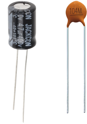
Electrolytic capacitors are ‘polarised’ which means they have a positive and negative lead and must be positioned in
a circuit the right way round (the positive lead must go to the positive
side of the circuit).
They also have a much higher capacitance than non-electrolytic capacitors.
Non-electrolytic capacitors usually have a lower capacitance.
They are not polarised (do not have a positive and negative lead) and
can be placed anyway round in a circuit.
They are normally used to smooth a current in a circuit.
CAPACITANCE - means the value of a capacitor.
Notice the electrolytic
capacitors above. They all have two polarised leads, in other words they
have a positive and negative leg. This type of capacitor is used with ICs
such as the 555 timer chip and it is the capacitors and resistors that
determine the timing sequence.
Look carefully at the photographs of the two types of
capacitors. Can you work out which one is electrolytic and which is non-electrolytic ?
The simple circuit (follow link below) is basically a switch which is
connected to a computer. When the switch is pressed the computer detects
that the relay is closed and then turns on a motor.
However, there is a problem. When the switch is pressed it only closes the
relay for a split second and this is not enough time for the computer
program to detect that it has been pressed in the first place. A time delay
is the obvious answer and this can be achieved by adding a capacitor in
parallel to the switch. If the relay is held closed for 3/4 seconds then the
computer program will have time to detect it - A capacitor provides the time
delay.
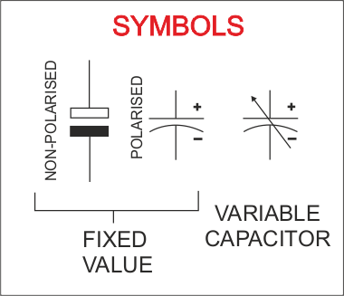
REMEMBER - there are
polarised and non-polarised capacitors. Look for a positive and negative
sign.