| CLICK HERE FOR INDEX PAGE | |
| EXAMPLE LOGIC CIRCUITS - 1 | |
| V. Ryan © 2003 - 2017 | |
|
PDF FILE - CLICK HERE FOR PRINTABLE WORKSHEET BASED ON EXERCISE BELOW |
|
|
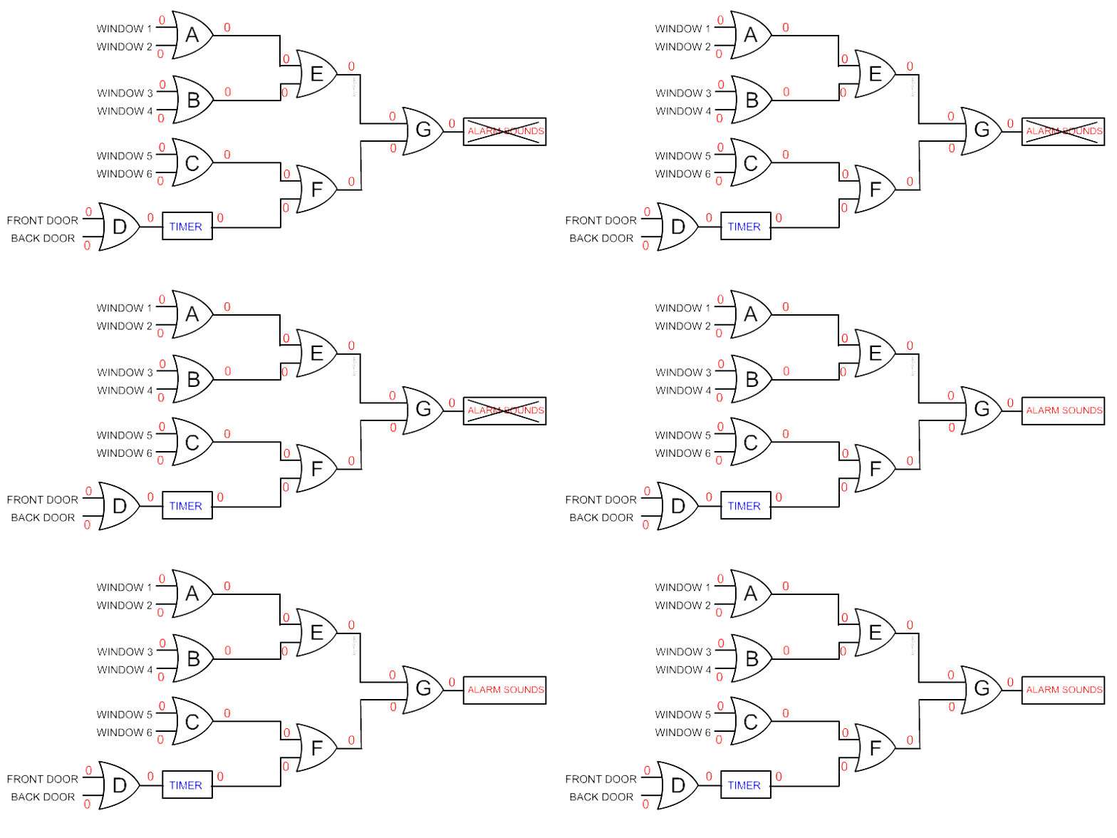
Below is the logic circuit for a simple house alarm.
The alarm protects the front and back doors and six windows. Once the
alarm is set if any of the doors or windows are opened the alarm will
sound. OR gates have been used. The TIMER
allows the house owner to enter the house by either the front or back
door and turn of the alarm system before the alarm sounds. |
|
|
|
|
|
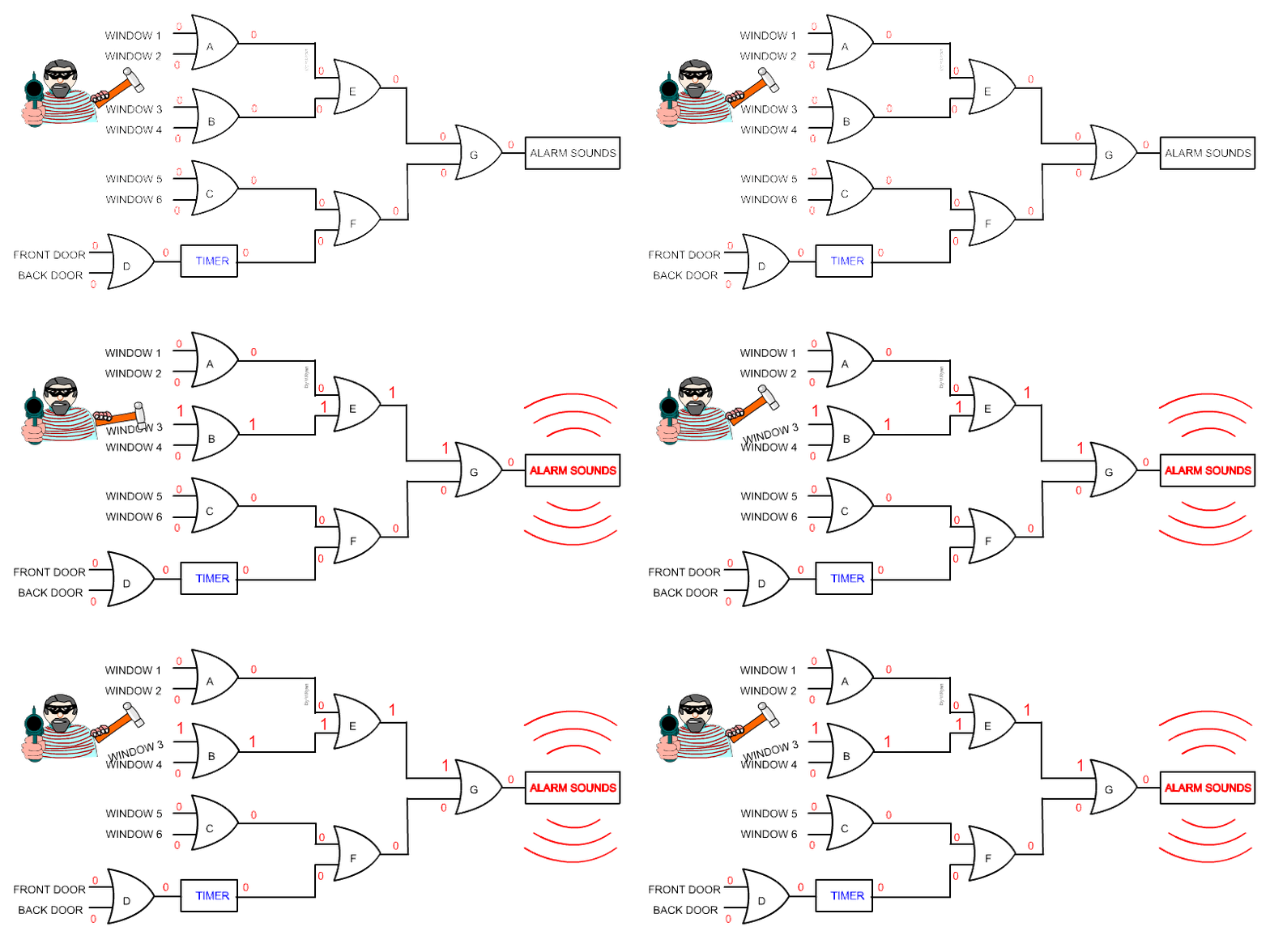
The situation changes when local thug, Ed the Handyman forces window 3 open. Notice how the logic state of the input of GATE B changes from false to true. The output state of gate ‘B’ changes to true, followed by the INPUT of gate ‘E’ and its output. The input and output of gate ‘G’ also change to true. This train of events leads to the alarm sounding. Because OR gates have been used, it only takes one input to change to true at the windows or doors to activate the alarm. |
|
|
|
|
|
|
|

