| CLICK HERE FOR INDEX PAGE | |||||||
| DUAL TRANSISTOR MULTIVIBRATOR CIRCUIT | |||||||
| V. Ryan © 2004 - 2022 | |||||||
| PDF FILE - CLICK HERE FOR PRINTABLE WORKSHEET BASED ON EXERCISE BELOW | |||||||
|
A multivibrator circuit is a circuit that has identical components arranged on the left and right hand sides. In the case of the example below, the two PNP transistors, the capacitors and the LEDs are the key components. This circuit will trigger itself repeatedly and in this way the LEDs flash alternately. Increasing the value of the two electrolytic capacitors increases the time each LED remains on/off. The transistors are general PNP type. It is important to protect the LEDs and this is achieved by adding the 680R (or lower if necessary) fixed resistors. |
|
||||||
|
|
|||||||
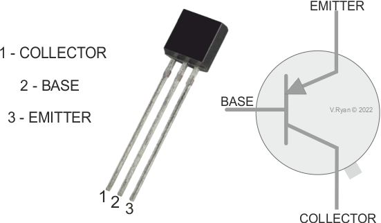
| TYPICAL PNP TRANSISTOR | |||||||
 |
|||||||
| PICTORIAL REPRESENTATION OF THE MULTIVIBRATOR CIRCUIT | |||||||
 |
|||||||
|
As the switch is pressed, the capacitors charge up and then discharge. As one capacitor charges the other discharges. As the capacitors discharge, each triggers the base of the transistor it is connected to. This allows current to pass from the collector to the emitter and the LEDs light, alternately. |
|||||||
|
|||||||
|
QUESTIONS: 1. Name the two most important components in the multivibrator circuit shown above. 2. What would be the effect of increasing the values of both capacitors? |
|||||||
|
|
|||||||