| |
| CLICK HERE FOR INDEX PAGE |
| |
| EXAMINATION QUESTION - JIGS |
| |
| V. Ryan © 2006 - 2009 |
| |
| PDF FILE - CLICK HERE FOR PRINTABLE VERSION OF
QUESTIONS |
| |
1. The diagram below shows a jig used on a production
line to check the length of a component (the steel cylinder).
When the steel cylinder is inserted into the test jig, the green LED
lights. This shows that the steel cylinder is the correct length. |
| |
 |
| |
|
|
| |
The push to make switches control the LEDs.
If switch ‘C’ is not pressed none of the LEDs should light.
The red and green LEDs indicate whether the cylinder is the correct
length, too short or too long.
If the cylinder is too long it will press switches A, B and C. The RED
and GREEN LEDs will light.
If the cylinder is too short it will not press switches A and B.
If the cylinder is the correct length both switches B and C should be
pressed. |
| |
 |
| |
1a. In the space
below draw a circuit that shows how switches A, B and C can be connected
to make the jig and its LEDs work correctly.
include all three switches, the green and red LEDs and appropriate
resistors (include values) |
| |
 |
| |
| POSSIBLE ANSWER |
| |
 |
| |
|
|
| |
| 1b. Explain the purpose of the
resistors. |
| |
| |
| |
| |
| |
| POSSIBLE ANSWER |
| |
| The resistors protect the LEDs. They reduce the flow
of electricity allowing the LEDs to light rather than be damaged.
Without the resistors the LEDs would ‘blow’ |
| |
| 1c. What is the advantage of using a
9 volt power source for the jig? |
| |
| POSSIBLE ANSWER |
| |
| A 9 volt power source means that the jig is
electrically safe as electrocution of the operator cannot take place
even if there is s fault. The 9 volt supply can be from a battery making
the jig mobile and not requiring a mains electric connection. |
| |
| 1d. In the space below draw a ‘push
to make switch’ and describe how it works. |
|
| |
| |
| |
| |
| |
| POSSIBLE ANSWER |
| |
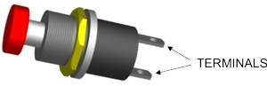 |
| As the switch is pressed a connection is made across
the two terminals allowing electricity to flow around the circuit. |
| |
| 1e. Draw and label two other types
electro mechanical switch. |
|
| |
| POSSIBLE ANSWER |
| |
 |
| |
|
|
| |
| CLICK HERE FOR ELECTRONICS INDEX PAGE |
| |