| CLICK HERE FOR INDEX PAGE | |||||||||||||||
LIGHT / DARK SENSOR - ANIMAL FEEDER CIRCUIT AND REVERSING A MOTORS DIRECTION OF ROTATION |
|||||||||||||||
| V. Ryan © 2006 - 2019 | |||||||||||||||
|
PDF FILE - CLICK HERE FOR PRINTABLE VERSION OF EXERCISE SEEN BELOW |
|||||||||||||||
|
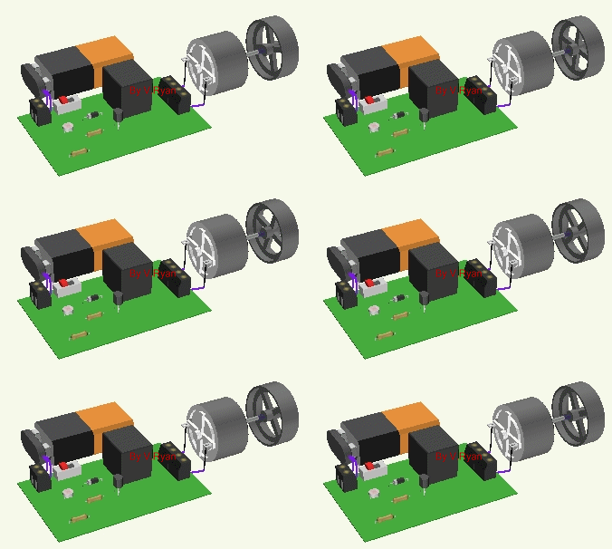
The sensor below is a light/dark sensor. This is part of an automatic animal feeder. As it becomes dark the sensor activates a relay that in turn turns on a motor, rotating a fly wheel. The fly wheel operates a mechanical system that releases food to a small animal, such as a hamster. Food is release during the night. This is electronics simulation software which allows the designer to draw a circuit in 3D and test it for faults. |
|||||||||||||||
 |
|||||||||||||||
| The circuit below shows how a LDR can be used to reverse a motor. This may be useful in certain practical applications. For example, If an animal feeder has a lid that opens to reveal food and then closes, after a short time. The lid could be controlled by a motor, which in turn could be controlled by a LDR circuit. | |||||||||||||||
|
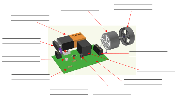
1. A list of component names are seen below the diagram. Write each of the component names in the correct place on the diagram. |
|||||||||||||||
 |
|||||||||||||||
|
|||||||||||||||
|
2. Only one transistor is used in this circuit. The electronics simulation software 'Crocodile Technology 3D' has identified a possible fault - sometimes it is wise to include two transistors called a ‘darlington pair’ rather than the one transistor shown in the diagram above. Draw below a circuit diagram representing a darlington pair. |
|||||||||||||||
|
|
|||||||||||||||
| 3. Why is it wise to use a darlington pair (two transistors) rather than a single transistor? | |||||||||||||||