Below are some examples of 741 I.C. based circuits.
However, this time the 741 is used as a comparator and not an amplifier.
The difference between the two is small but significant. Even if used as
a comparator the 741 still detects weak signals so that they can be
recognised more easily. It is important to understand these circuits as
they very regularly appear in examinations.
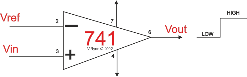
A ‘comparator’ is an circuit that compares two input
voltages. One voltage is called the reference voltage (Vref) and
the other is called the input voltage (Vin).
When Vin rises above or falls below Vref the output
changes polarity (+ becomes -).
Positive is sometimes called HIGH. Negative is sometimes called LOW.
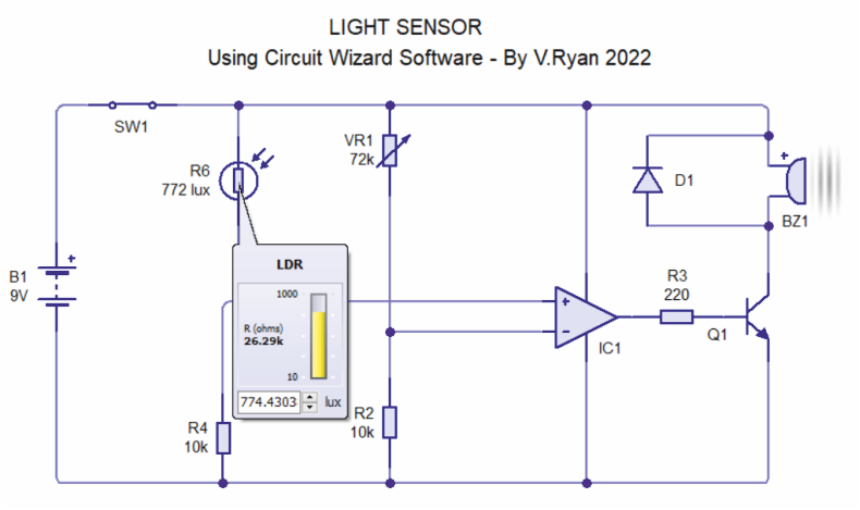
EXAMPLE CIRCUIT - LIGHT ACTIVATED ALERTER
The buzzer emits a tone when light falls on the light
dependent resistor. Resistor 2 controls the sensitivity of the circuit.
The 741 is working as a comparator and the piezo buzzer sounds when the
output form the 741 goes ‘low’ or in other words, changes from a
positive to a negative.
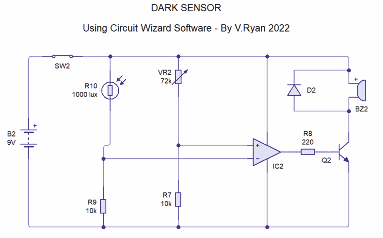
An alternative layout to a light / darksensor is seen below.
EXAMPLE CIRCUIT - DARK ACTIVATED ALERTER
This is a dark activated circuit, the reverse of the
circuit above. Do you notice the difference ? Changing round the connections at pins 3 and 2 (POS and NEG), reverses the function. Compare the connection on this circuit with the Light Sensor Circuit higher up the page.
Replace the LDR with a thermistor for a temperature circuit.
Below is a temperature sensor based on a 741 comparator circuit.
PICTORIAL REPRESENTATION OF THE TEMPERATURE SENSOR