| |
| CLICK HERE FOR INDEX PAGE |
| |
| THE THERMISTOR |
| V. Ryan © 2002 - 2022 |
| |
| PDF FILE - CLICK HERE FOR PRINTABLE VERSION OF
EXERCISE SHOWN BELOW |
| |
| |
 |
|
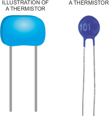
An example of a thermistor is seen to the left. They
are made up of a mixture of sulphides or oxides or sometimes metals such
as copper, iron or cobalt. They tend to be formed into a disc or a bead
sealed with plastic or glass.
They have great resistance at low temperatures but when they warm up
their resistance decreases rapidly. Current can then flow through them.
This makes them ideal as one of the components for a temperature sensor. |
| |
|
|
| |
WHEN THE THERMISTOR IS COLD RESISTANCE IS HIGH AND CURRENT CANNOT PASS THROUGH. WHEN WARMED, RESISTANCE FALLS AND CURRENT PASSES THROUGH.
(See Below) |
| |
 |
| |
A simplified circuit is shown below. When the
thermistor is cool or cold the LED should not light because of the high
resistance.
However, warm up the thermistor by blowing warm air from a hair drier
across it. This should warm it sufficiently that in a few seconds the
resistance will drop and the LED will light. |
| |
 |
|
Circuit explanation in detail:
When the thermistor is warmed up by the hair drier its resistance drops,
this will take a few seconds. As its resistance drops current begins to
flow from positive 9 volts to negative 0 volts. Current flows into the
base of the transistors allowing the LED to light.
The
preset resistor can be turned up or down to increase or decrease
resistance, in this way it can make the circuit more or less sensitive. |
| |
|
|
| |
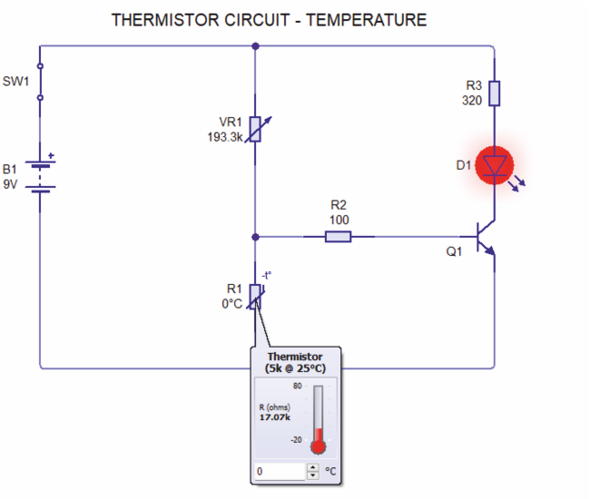
| In the next circuit, the preset resistor and thermistor have swapped position. The circuit is now a ‘cold’ sensor. The LED illuminates when the temperature drops to near zero degrees. It could be used as an ice sensor for a car. |
| |
| CIRCUIT WIZARD SIMULATION OF A COLD SENSOR |
| |
 |
| |
| PICTORIAL REPRESENTATION OF THE COLD SENSOR |
| |
 |
| |
| FURTHER
DETAIL - THE THERMISTOR |
| |
A thermistor’s resistance varies, determined by temperature. A 30R
@ 25oC thermistor, will have a range of resistance, from 37.13 ohms to
3.26 kilo ohms.
The animation below shows the range of resistance of a 30R @ 25oC thermistor. The thermistor can have numerous
resistance values, depending on the temperature applied to it. |
| |
Using Circuit Wizard
software, the resistance value / temperature of a thermistor can be
altered.
The 30R @ 25oC thermistor has a resistance of
37.13R resistance at 80 oC.
The 30R @ 25oC thermistor has resistance of 3.26K
resistance at -20 oC.
The
resistance is altered by using the computer’s mouse, to raise or lower the
thermistor’s resistance/temperature. |
| |
 |
| |
|
|
| |
| Below is
a more complicated circuit. It is a programmable circuit called a PIC
microcontroller. The thermistor is the input. When the temperature
drops, the thermistors resistance rises rapidly. The microcontroller
circuit detects this rise in resistance switches on two outputs. This
means that the LED illuminates and the solenoid energises. When the
temperature rises, the microcontroller switches the two outputs off, the
LED fades and the solenoid returns to its normal state. |
| |
 |
| |
| CLICK HERE FOR ELECTRONICS INDEX
PAGE |
| |
| |