Components:
680 ohm resistor to protect the LED.
1K resistor from LDR to the base of the NPN transistor.
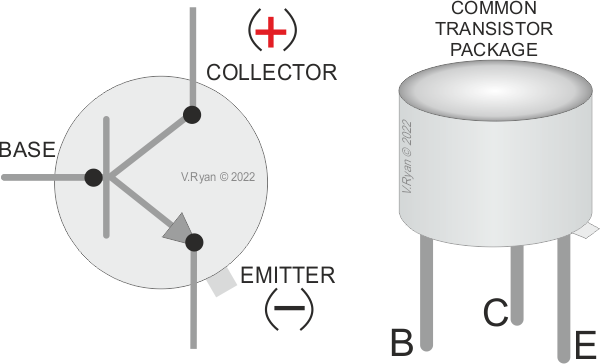
One BFY50 npn transistor (try any alternative).
One 10K preset resistor.
One LDR.
How it works:
When light shines into the LDR its resistance is high and consequently current cannot flow from positive 9 volts to negative 0 volts. If the LDR is completely covered its resistance falls dramatically. Current then flows into the base of the transistor switching it on. Consequently current can flow through the collector and emitter - therefore, the LED lights.
2. Try building a light sensor, that is a circuit in which the LED lights if light shines into the LDR. HINT; try swapping round the LDR and the preset resistor.
3. Try building a similar circuit but this time add an arrangement of transistors called a Darlington Pair. Do you find any difference in the operation of the circuit ?
4. Try building a similar dark sensor but this time with a relay rather than an LED.