| |
| CLICK HERE FOR INDEX PAGE |
| |
| 741 OPERATIONAL AMPLIFIER COMPARATOR EXAMINATION QUESTION AND INFORMATION |
| |
| V. Ryan © 2007 - 2022 |
| |
| PDF FILE - CLICK HERE FOR PRINTABLE VERSION OF EXERCISE
SEEN BELOW |
| |
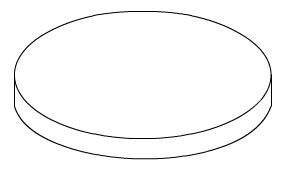
| A home-made anemometer can be seen below.
It is part of a system that calculates the wind speed. It is composed of
four cups that rotate on a central shaft. As it rotates a light / dark
sensor, housed in the sensor bracket detects light from the light bulb
found inside the sensor bracket. The sensor is connected to a circuit that
counts each time the disk rotates (light from the bulb is detected). |
| |
 |
| |
|
|
| |
 |
| |
 |
| |
| NOTES |
| |
| |
| |
| |
| SAMPLE
ANSWER |
| |
 |
| |
| NOTES |
| |
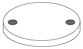
| As the disk spins the light from the bulb shines through
the two holes in the disk as it rotates. The sensor detects the light. The
circuit it is connected to counts each time light is detected. |
| |
|
|
| |
| 2. Below is a 3D version of the sensor / counter
circuit. |
| |
 |
| |
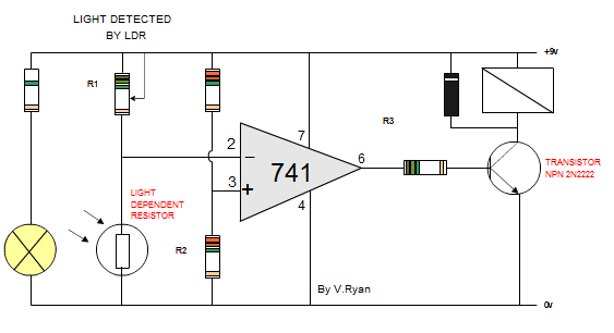
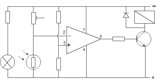
| The circuit diagram of the 3d circuit is seen below.
When the light from the bulb shines on the light / dark sensor the
resistance of the LDR decreases. This allows current to flow into pin 2.
The 741 compares the current of pin 2 and pin 3. When a change in current
occurs in either pin 2 or 3 the 741 outputs current at pins 6. This
energises the relay. The energised relay activates the counter circuit.
Each time the counter circuit is activated it adds a number. |
| |
 |
| |
| However, there is a fault with the circuit due to the
position of the light bulb and LDR. Sometimes the LDR does not detect the
light from the bulb. Explain why this may happen and how it could be
corrected. |
| |
| 3. WHY THE LIGHT IS NOT ALWAYS DETECTED: |
| |
| |
| |
| |
| |
| POSSIBLE ANSWER |
| |
| The bulb is not directly above the LDR. This means that
much of the light from the bulb shines away from it. |
| |
| 4. HOW THE CIRCUIT COULD BE CORRECTED SO THAT
LIGHT IS ALWAYS DETECTED: |
| |
| |
| |
| |
| |
| |
| POSSIBLE ANSWER |
| |
| The LDR could be moved so that the light shines
directly into it. This will reduce the resistance of the LDR so that
current flows through the circuit energising the relay. |
| |
|
|
| |
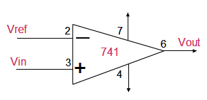
| 5. A 741 Operational Amplifier is represented by a
distinctive symbol. Draw the symbol in the space below |
|
| |
| POSSIBLE
ANSWER |
| |
 |
| |
| The sensor circuit has been altered slightly and it is
now suitable for use in the sensor bracket. The LDR is not soldered
directly to the PCB as it is fixed in position with a electrical
connector. This means that the LDR is directly above the bulb. As the bulb
lights the LDR detects the light immediately. |
| |
 |
| |
| 6. How does the position the LDR in relation to the bulb
make the circuit more efficient ? |
| |
| |
| |
| |
| |
| POSSIBLE
ANSWER |
| |
| The circuit is more efficient because light from the
bulb shines directly into the LDR. Light is either present or not present.
The circuit is now an accurate light / dark sensor. |
| |
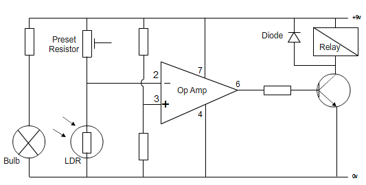
| 7. Identify the components listed below (label the
components on the circuit diagram) : |
| |
| Preset Resistor - Op Amp - Diode -
LDR - Bulb - Relay |
| |
 |
| |
| POSSIBLE
ANSWER |
| |
 |
| |
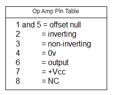
| 8. Label the 741 Op Amp shown in the circuit above
according to the Pin Table shown below. |
| |
 |
| |
| CLICK HERE FOR ELECTRONICS INDEX PAGE |
| |