| A digital input device
such as a push switch, is either on or off. It has two states. An analogue
signal, is a constant signal that varies in ‘strength/weakness’.
Components such as light dependent resistors, are useful as analogue
sensors. This is because their resistance varies, typically from 1000 000
ohms to 400 ohms. This gives thousands of possible states. Resistance values of an LDR are shown below . The LDR can have thousands of resistance values, depending on the light level. |
| Circuit Wizard software has been used
to display, the range of values of a ORP12, LDR . When a light level of 1000 lux (bright light) is directed towards it, the resistance is 400R (ohms). When a light level of 10 lux (very low light level) is directed towards it, the resistance has risen dramatically to 10.43M (10430000 ohms). |
 |
| The typical use of an
LDR, as an analogue input device is shown below. It is being used as an
analogue input, for a GENIE E18 PIC microcontroller circuit. The circuit
has been programmed to illuminate an LED and to energise a solenoid, when
the light level drops below a particular level. Diagram ‘C’ shows the complete circuit and the various light levels / resistance of the LDR, analogue sensor. When the light level is low, the resistance of the LDR is high. The microcontroller has been programmed to illuminate the LED and energise the solenoid, when the resistance of the LDR is high. |
 |
| (Circuit produced using Circuit Wizard software) |
| The drawing below shows
a very similar GENIE E18 circuit, called the GENIE E18 Project Board.
Unlike the circuit diagram shown above, this circuit includes a driver
chip. The input A/D1 has an LDR connected. The outputs Q0 and Q7, have an LED and a solenoid as outputs. This is the same arrangement as the circuit diagram. |
 |
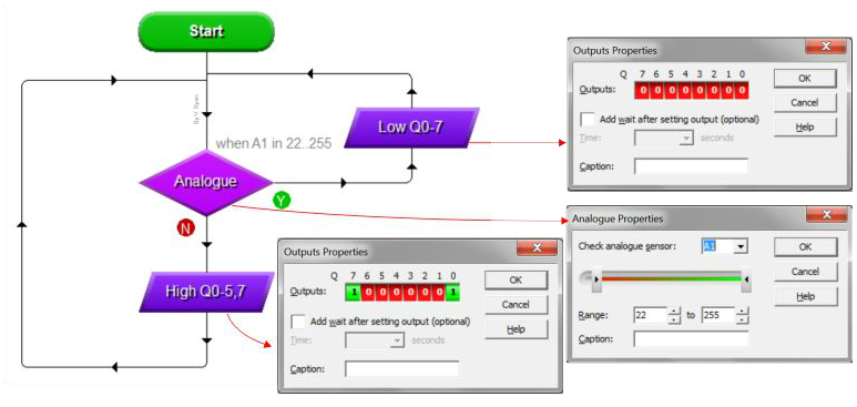
| PROGRAMMING - ANALOGUE INPUT |
| Circuit Wizard, ensures
that programming an analogue input is easy and straightforward. The flow
chart below, has been constructed to control the previous GENIE E18
microcontroller circuit (above). The LDR analogue input, is connected to A/D1. This input is continually monitored by the GENIE E18 (see Analogue box of the flow chart). When the light levels falls outside a range (22 - 255), the microcontroller outputs current at outputs Q0 and Q7. This means that the LED illuminates and the solenoid energises. |
 |
| CLICK HERE FOR PIC-MICROCONTROLLER INDEX PAGE |