| CLICK HERE FOR INDEX PAGE |
| |
| TURRET TOOLING, GANG TOOLING AND LIVE TOOLING |
V.Ryan © 2020-2023 |
| |
| PDF FILE - CLICK HERE FOR PRINTABLE WORKSHEET |
| |
| CLICK HERE FOR POWERPOINT VERSION OF WORKSHEET |
| |
| TURRET TOOLING |
| |
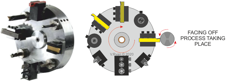
| A CNC Turning Centre normally has a more complex ‘tool post’, than one found with a basic lathes. This allows the CNC to be used for more complex work, without the need to constantly change lathe tools manually. A turret tool system is seen below. A variety of tools are set up on a rotating turret. This means that a variety of machining processes can be carried out. For example, a straight lathe tool may be needed for facing a piece of round section mild steel, followed by drilling. The CNC machine is programmed to carry out the facing off first, then to rotate the turret, so that drilling can follow. |
|
 |
| |
|
|
| |
 |
| |
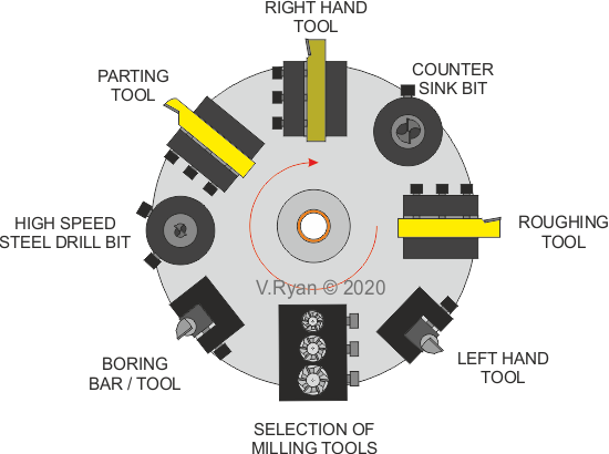
| Below is a typical arrangement of tools, set up on a turret tooling system. This allows for a combination of lathe and milling processes to take place, without the need to manually change tools. It is a very efficient machining system. |
| |
 |
| |
| GANG TOOLING USING A CNC CENTRE |
| |
An alternative to a turret tooling system is Gang Tooling. This system is another efficient tooling system for CNC Centres and lathes.
When using a typical engineering lathe, the tool post usually only holds one tool, which has to be changed, every time the machining processes changes.
Gang tooling requires the use of an extended tool post, which is secured to the cross slide of the lathe, with slotted bolts (see opposite).
The tool post holds a range of lathe tools. The cross slide moves the tool post and consequently each tool, into position, as needed for each machining process. Gang tooling, saves precious tool changing time. The CNC Centre, controls the movement of the cross slide and consequently the extended tool post. |
|
 |
| |
|
|
| |
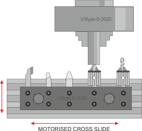
The diagram shown below, shows the operation of an extended tool post, set up for gang tooling.
The CNC is programmed to centre drill the steel section held in the chuck. The lathe bed then moves the second drill in position and a hole is drilled. The bed moves again, to allow the face of the steel to be ‘faced off’.
Other machining processes follow, with the lathe bed moving the extended tool post, positioning the correct tool, for the various machining processes. |
| |
 |
| |
| LIVE TOOLING |
| |
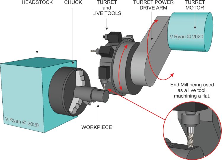
| On first sight, ‘Live Tooling’ looks the same as the turret system. However with this system, each tool can have its own motor. This means that milling processes can be applied to the metal being machined. Live tooling often takes place without the metal being machined moving, or even rotating in the chuck. Live tooling is ideal for milling type operations. |
| |
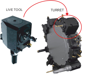
The live milling tool seen opposite, is an individual unit, with its own motor. It is just one of the live tools fitted to the turret.
The turret can be fitted with a variety of tools, either with their own motors or those that depend on the movement of the metal being machined, as it spins in the chuck of the CNC Centre. |
|
 |
| |
| The photograph below, shows one of the independently motorised milling tool attachment, ‘machining’ the surface of the workpiece. This is an ideal machining process for live tooling. The chuck does not rotate, when this process is carried out. The turret and turret power drive arm are manoeuvrable, allowing a the live tools to approach the workpiece, from a variety of angles. The manoeuvrability of the live tools dramatically increases the machining processes that can be achieved. |
| |
 |
| |
|
|
| |
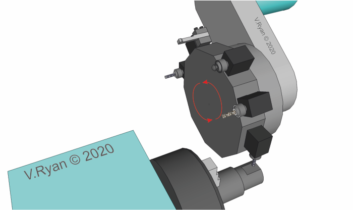
The reverse view of the turret with its live tools, shows a number of tools set up to perform a variety of machining processes.
When one process is carried out, the turret rotates in combination with the turret drive arm, putting the next tool in the right position, for the following machining process. |
| |
 |
| |
| |
| CLICK HERE FOR CNC INDEX PAGE |
| |
|
| |
|