| CLICK HERE FOR INDEX PAGE | |
| CRANK AND SLIDER MECHANISM | |
| V. Ryan © 2002 - 2020 | |
| PDF FILE - CLICK HERE FOR PRINTABLE WORKSHEET | |
|
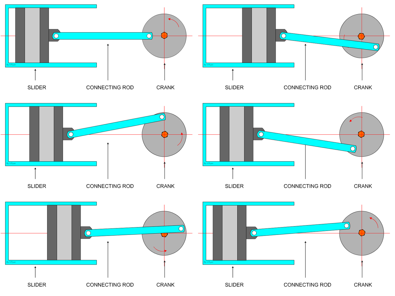
This mechanism is composed of three important parts: The crank which is the rotating disc, the slider which slides inside the tube and the connecting rod which joins the parts together. |
|
 |
|
|
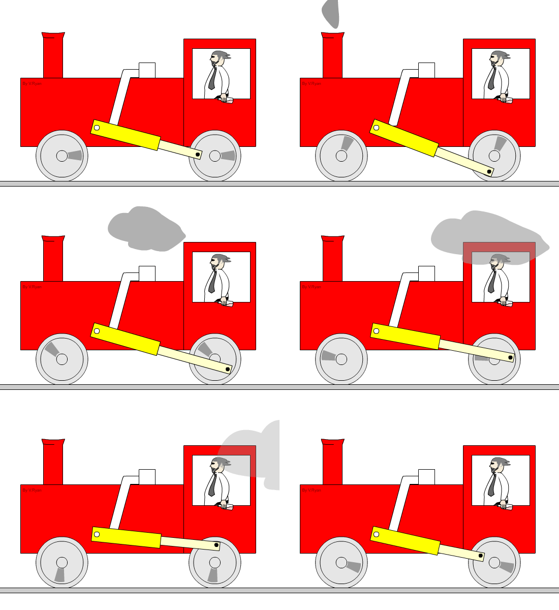
As the slider moves to the right the connecting rod pushes the wheel round for the first 180 degrees of wheel rotation. When the slider begins to move back into the tube, the connecting rod pulls the wheel round to complete the rotation. |
|
 |
|
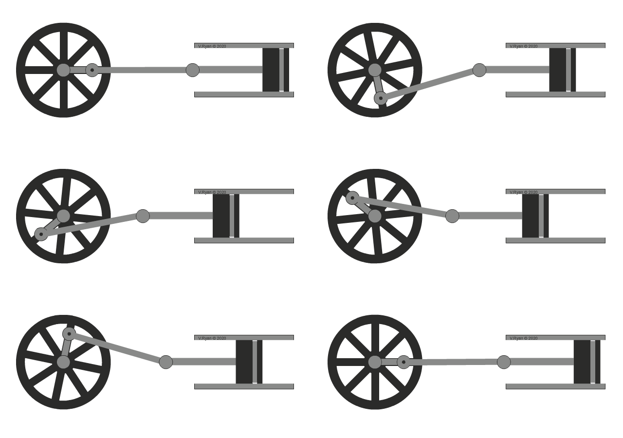
| Analternative layout to a Crank and Slider | |
 |
|
 |
|
|
|
|
|
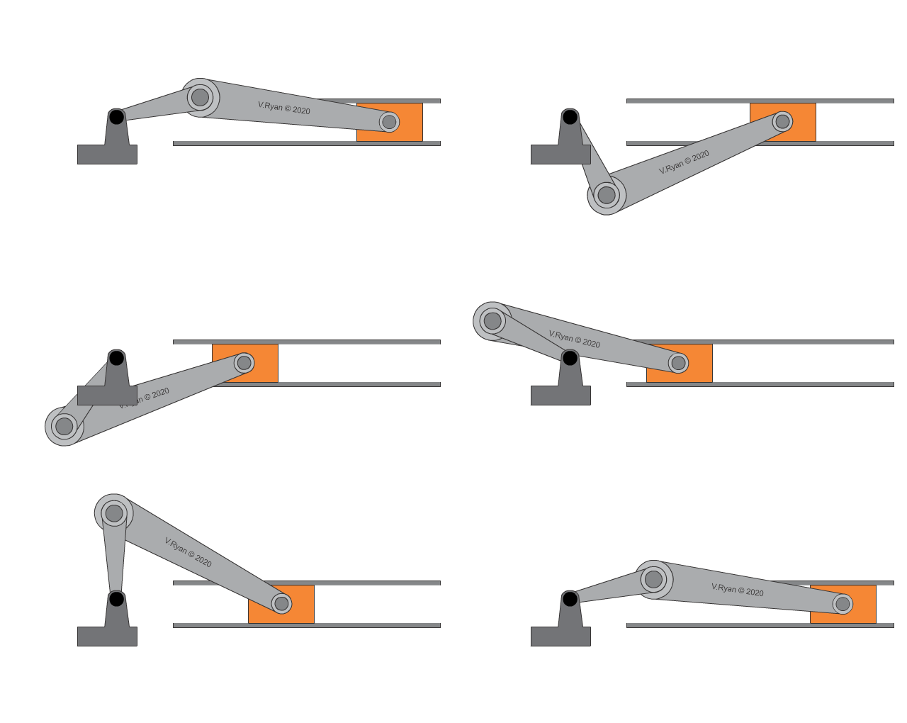
Find two more examples of crank and slider mechanisms, draw diagrams and use notes to explain how they work. |
|
|
|
|