Electronic timers are central to school projects. You
will find as you develop your circuits that the timer circuit can be adapted
to suit many purposes. There are several reliable timers but the 555 timer
is the most common. Whether you are putting together an alarm or a circuit
to activate a computer, a timer is the common component.
The 555 timer IC (integrated circuit) is very stable, relatively cheap and
reliable. It may be used as monostable or astable.
MONOSTABLE
Monostable means
that once the circuit is switched on it will time once and then stop. In
order to start it again it must be switched on manually a second time.
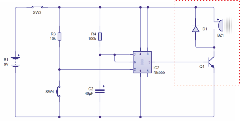
In the circuit drawn below, the 555 timer is set to
turn on the buzzer when the push switch is pressed; the buzzer sounds for
approximately 8 seconds. This is a monostable circuit as it works only once.
The switch must be pressed again for the buzzer to sound again.
CIRCUIT WIZARD SOFTWARE - SIMULATION OF CIRCUIT
PICTORIAL REPRESENTATION OF CIRCUIT DRAWN ABOBE
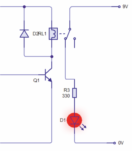
On the circuit diagram above, if the components 'boxed in' by the red dotted line are changed with the alternative components (shown on below) - the 555 timer circuit can be used to energise a relay.
The timer can now be used to trigger a relay which then allows another circuit to work. In this case the timer holds the relay closed for a preset amount of time, allowing the second circuit to work and then switches the relay open, which stops the secondary circuit and the light of the LED turns off.
SEE VIDEO BELOW
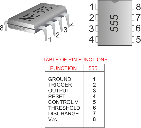
WHAT THE 'PINS' OF THE 555 ACTUALLY DO
The pin (leg) that triggers the 555 IC is leg two. In
other words leg two starts the timing sequence once a voltage is applied to
it and after the 555 timer has ended it’s timing sequence a signal (output)
is sent down leg three. In the circuit at the top of this page, the signal
down leg three starts the buzzer. The variable resistor VR1 can be used to
increase or decrease the timing cycle.