| |
| CLICK HERE FOR INDEX PAGE |
| |
| CONTROL SYSTEMS - AN EXAMPLE |
| |
| V. Ryan © 2003 - 2009 |
| |
| PDF FILE - CLICK HERE FOR PRINTABLE WORKSHEET BASED
ON EXERCISE BELOW |
| |
An
Automatic Sprinkler System
|
An automatic water sprinkler system
has been ordered by a farmer. The system must have sensors that detect
dry weather and turn on water sprinklers to water valuable crops.
The company manufacturing the system have decided that a starting point
is to think in terms of INPUT - PROCESS - OUTPUT and also include FEEDBACK.
The basic plan is set out below. |
| |
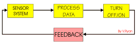
INPUT
How will the dryness of the soil be sensed? Perhaps an electrode
can be used. |
|
PROCESS
What device(s) will be needed to control the output? A computer
could monitor incoming data and control the output, a simple
program will be required. |
|
OUTPUT
This may be a sprinkler device which is turned on when the
computer detects the need for water. |
| |
|
|
|
|
| |
|
FEEDBACK
Feedback is constant as the computer continually checks the
moisture level of the soil. |
|
|
|
| |
|
|
| |
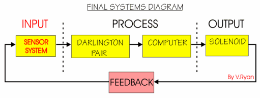
| This is the layout to the systems diagram for the
automatic sprinkler system. |
| |
 |
| |
| One Possible Answer: |
| |
 |
| |
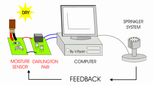
The moisture sensor detects when the soil is dry. The darlington pair is a simple electronic
device that amplifies the signal sent by the sensors so that the
computer can read it. Without the darlington pair it is possible that the signal from the sensor could be too weak to be
read by the computer. This would mean that the sprinkler system would
not be turned on.
When the sensor determines that the soil is moist/damp the signal to the
computer ends and the computer turns off the sprinkler. This is called FEED BACK. |
| |
 |
| |
|
|
| |
QUESTION:
Draw a systems diagram for a domestic alarm system. Show clearly input,
process and output. Explain the need for feedback. |
| |
| CLICK HERE FOR MORE INFORMATION
REGARDING CONTROL SYSTEMS |
| |
| CLICK HERE FOR ELECTRONICS INDEX
PAGE |
| |
| |
| |