When designing a control system it is good practice
to consider the overall system as a number of stages. For example;
A simple weather station can be looked upon as the following;

INPUT - the sensors (temperature, rain
fall, humidity etc..)
PROCESS - the computer that analyses the incoming data.
OUTPUT - the final printout of temperature etc....
The system above is a closed system because it has feedback.
A system that does not have feedback is an open system. The feedback in
this system constantly monitors the incoming data from the weather
sensors.
Example - Automatic Sprinkler System (for gardens):
INPUT - How will the dryness of the soil be
sensed? Perhaps an electrode can be used.
PROCESS - What device(s) will be needed to control the output? A
computer could monitor incoming data and control the output, a simple
program will be required.
OUTPUT - This may be a sprinkler device which is turned on when
the computer detects the need for water.
FEEDBACK - Feedback is constant as the computer continually
checks the moisture level of the soil.
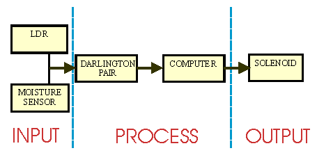
The LDR and the moisture sensor sense when water is needed. The Darlington pair is a simple electronic device that amplifies the signal sent by the sensors so that the computer can read it. The computer program then operates the solenoid, turning on the sprinkler which waters the soil.
INPUT DEVICES
The table below lists a number of INPUT devices. These can be either digital sensors or analogue (see analogue/digital section) and a 'system' normally starts with one of these.
|
INPUT DEVICES |
SENSES/MEASURES |
| Light dependent resistors | light |
| Phototransistors | light |
| Thermocouples | temperature |
| Thermistors | temperature |
| Potentiometers | movement |
| Electrodes | humidity |
| Microphones | sound |
| Strainguages | strain/bending |
| Switches | manual/mechanical |
PROCESSING DEVICES
The table below lists a number of PROCESSING devices. These include computers and microprocessors as they are often used to detect a signal from a sensor.
| PROCESSING DEVICE |
EXAMPLE |
| Amplifiers | amplifies small inputs |
| Electronic switches | switches at different levels |
| Timers | switches after time delay |
| Gates; and/nand/or/nor | combines inputs |
| Counters | counts input pulses |
| Computer | detects the signal from input device |
| Micro-processor | detects the signal from input device |
OUTPUT DEVICES
The table below lists a number of OUTPUT devices. These are usually devices such as motors or buzzers. For example, the output to an alarm system will be a buzzer or siren sounding.
| OUTPUT DEVICES |
EXAMPLE |
| Relays | controls higher voltages/circuits |
| Lamps | light |
| Buzzer/Bells | sound |
| Speakers | sound |
| Motors | movement (rotary) |
| Stepper motors | movement (precise rotary) |
| Solenoids | movement (linear) |
| Indicators | information |
Circuits are usually designed throught the systems approach as they usually have INPUTs a PROCESS and OUTPUTs.
CLICK HERE TO SEE AN EXAMPLE OF A CIRCUIT DISPLAYED AS A SYSTEM