| CLICK HERE FOR INDEX PAGE | |
| DIGITAL ELECTRONICS - BASIC LOGIC TABLES | |
| V. Ryan © 2003 - 2009 | |
|
PDF FILE - CLICK HERE FOR PRINTABLE WORKSHEET |
|
|
A range of logic gates exist and they are represented
as symbols, each with its own truth table (sometimes called a logic
table). Gates have inputs and produce outputs and these are in the form
of 1s and 0s.
Remember, a 1 represents an input or output
of electrical current. Each truth table clearly shows the ‘state’ of
inputs and outputs at any one time. |
|
|
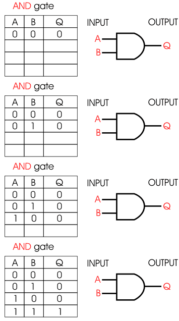
The AND gate will only output current (produce a 1 at Q) if both logic states at inputs A and B change to 1. |
|
|
|
|
|
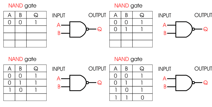
The NAND gate has the opposite outputs to the AND gate. How does the NAND gate symbol differ to the AND gate? |
|
|
|
|
|
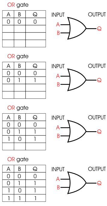
The OR gate will output current at Q if either of the logic states of inputs A and B change to1. |
|
|
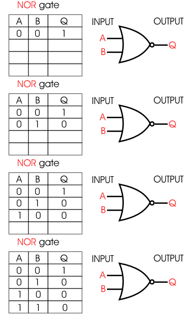
The NOR gate has the opposite outputs to the OR gate. How does the NOR gate symbol differ to the OR gate? |
|
|
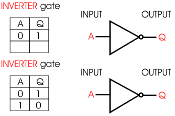
The INVERTER gate
reverses input. For example, if the input is 1
then the output is 0. |
|
|
QUESTIONS: |
|
|
|
|
