| CLICK HERE FOR INDEX PAGE | |
| DIGITAL LOGIC EXAMINATION QUESTION - 2 | |
| V. Ryan © 2004 - 2009 | |
| PDF FILE - CLICK HERE FOR PRINTABLE VERSION OF EXERCISE SEEN BELOW | |
|
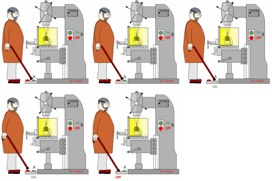
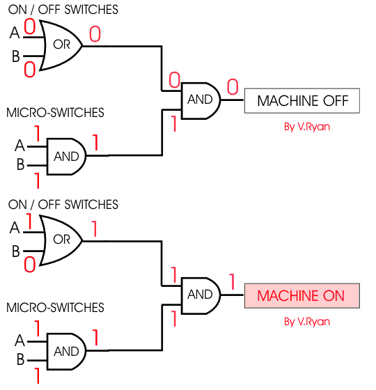
1A. A metal
cutting milling machine has two switches, any one will allow the cutter
to run. The first switch is on the side of the machine and the second is
a foot operated switch. |
|
|
|
|
|
|
|
|
1B. What moving
parts would you expect to see behind the door leading to the internal
mechanism of the milling machine? Why would access to this area be
dangerous if the machine is working at the same time? |
|
|
1C. Is having an ON and OFF switch on the floor a good idea? How would you improve the design of the switch to make the machine safer to use?
|
|
|
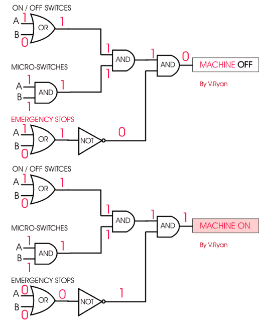
1D. The room has two emergency stop buttons at either end of the workshop. If either of these are pressed all machinery in the room will stop. Draw the new logic circuit for this arrangement of buttons and switches. |
|
|
|
|
|
|
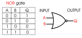
The NOR gate seen opposite could replace the OR and NOT gates, for the monitoring the emergency stops buttons. |
|
|
|


