| CLICK HERE FOR INDEX PAGE | |
| DIGITAL LOGIC EXAMINATION QUESTION - 3 | |
| V. Ryan © 2004 - 2009 | |
|
PDF FILE - CLICK HERE FOR PRINTABLE VERSION OF EXERCISE SHOWN BELOW |
|
|
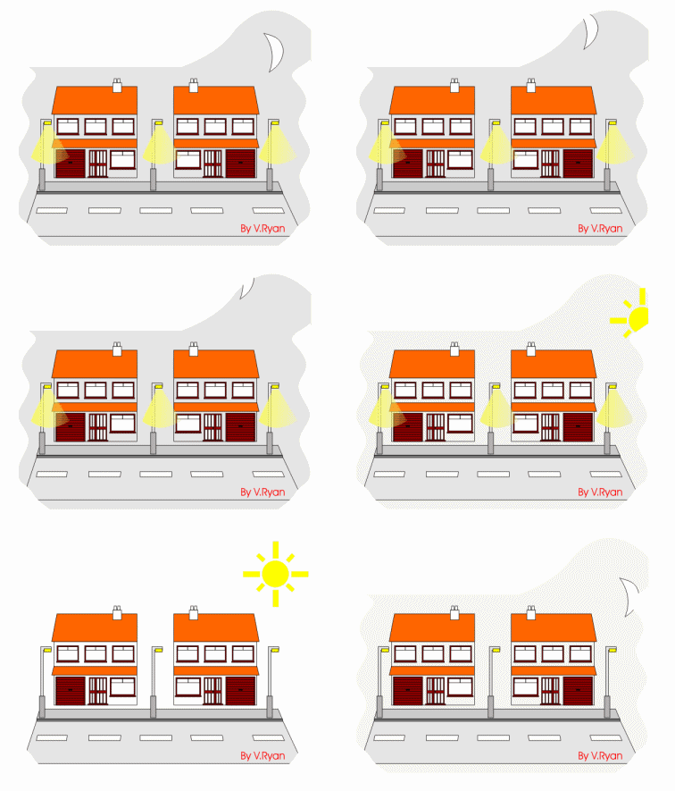
1. A local systems designer has developed a system to control street lights. The street lights can be turned on manually, or by the use of a timer, so long as a light sensing unit indicates that it is dark. |
|
|
|
|
|
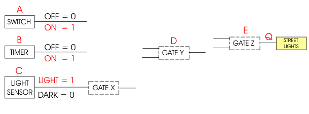
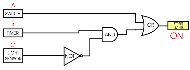
1A. Below is an incomplete logic circuit for the control system. Redraw the logic circuit using the correct logic gates. Note the output of the dark/light sensor is 1 (true, high, on) when it is light. The lights must be turned during the dark of night. |
|
|
|
|
|
|
|
| 1B. Name the logic gates you have used: | |
|
GATE X ................. |
|
|
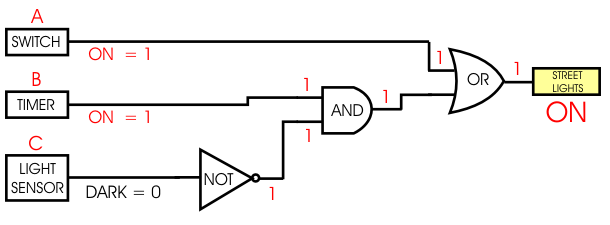
Below is the logic circuit showing the logic states of inputs and outputs of all the gates when the street lights are ON. |
|
|
|
|
|
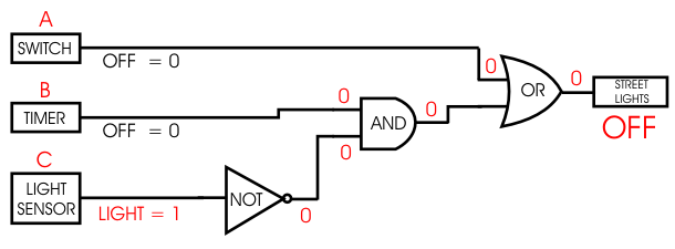
Below is the logic circuit showing the logic states of inputs and outputs of all the gates when the street lights are OFF. |
|
|
|
|
|
1C. On the logic
circuit below, write the logic states of all inputs and outputs for the
following: |
|
 |
|
| 1D. Complete the truth table for the logic circuit that controls the street lighting system. | |
|
|
|
| 1E. Normally a logic circuit such as the one used to control the street lights cannot power lights. In the space below name the subsystem that could be used. | |
|
|
|
|
|
|
