| CLICK HERE FOR INDEX PAGE | |
| THE THYRISTOR - BREADBOARD CIRCUIT | |
| V. Ryan © 2005-2022 | |
|
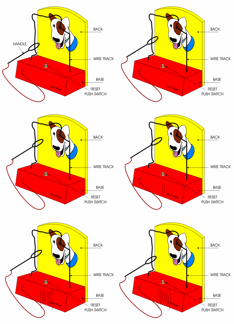
A Steady Hand Game is shown below. The aim is to move the handle around the wire shape without touching it. If the handle touches the wire a buzzer sounds. This is the type of game that contains a thyristor circuit. When the handle touches the wire the buzzer will sound until the reset push switch is pressed, even if the handle is moved away from the wire. |
|
 |
|
|
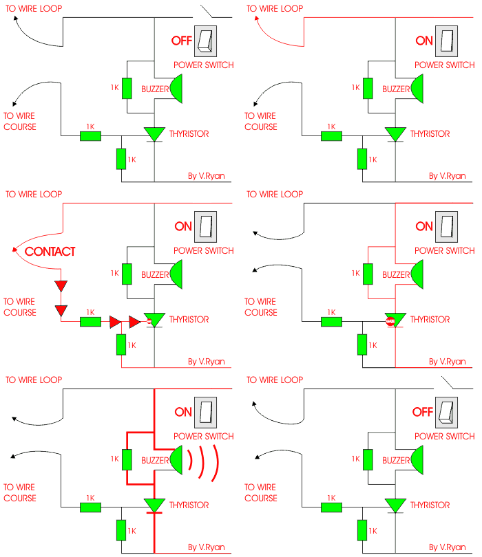
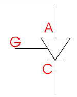
The circuit for this type of game is shown below. The main
component is called a thyristor. This is a special type of switch. When
it is activated it cannot be turned off unless electrical power is
removed from the whole circuit. |
 |
|
|
1. Using circuit
simulation software draw the thyristor circuit. |
| PICTORIAL REPRESENTION OF THE THYRISOR CIRCUIT | |
 |
|
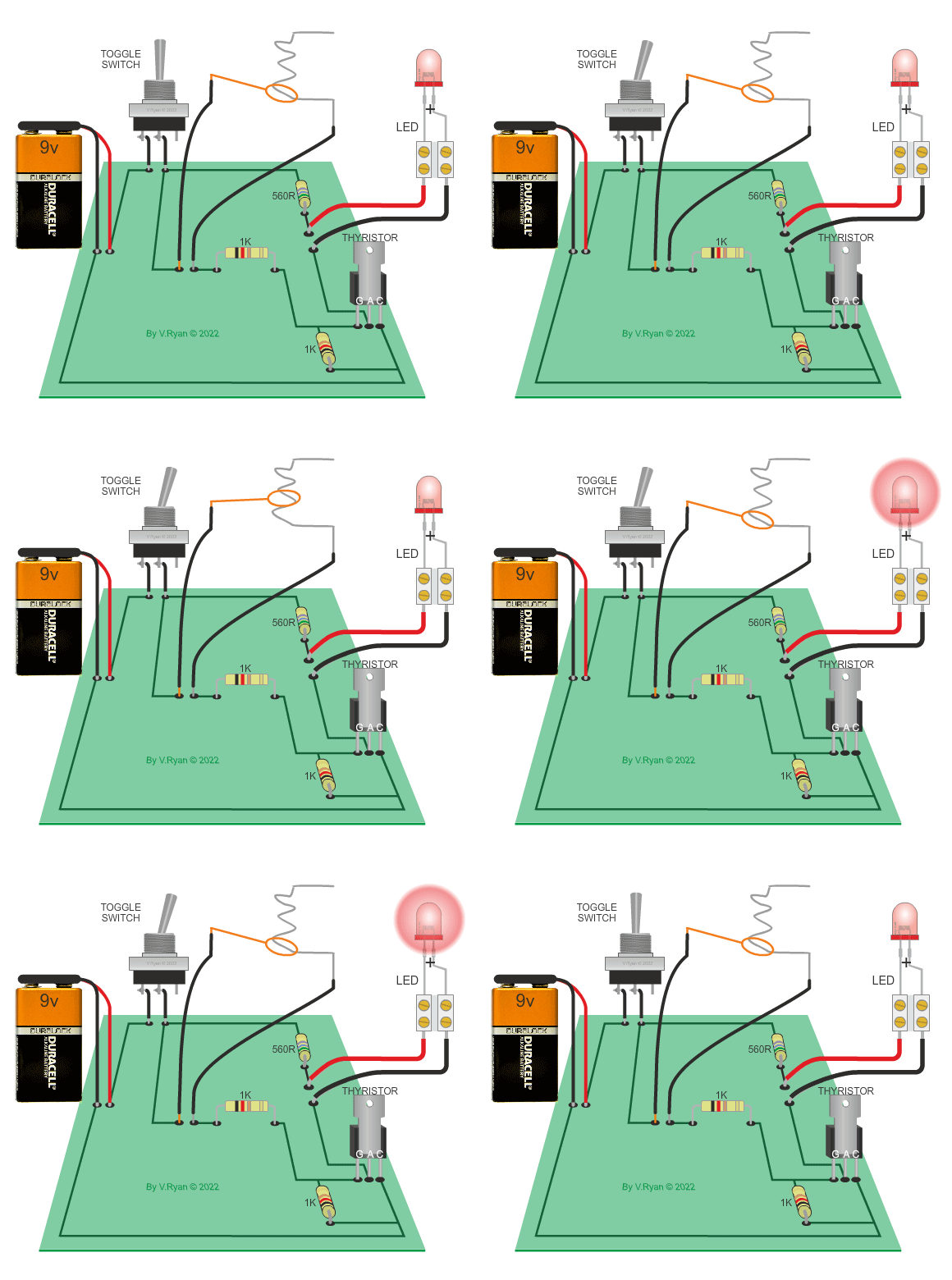
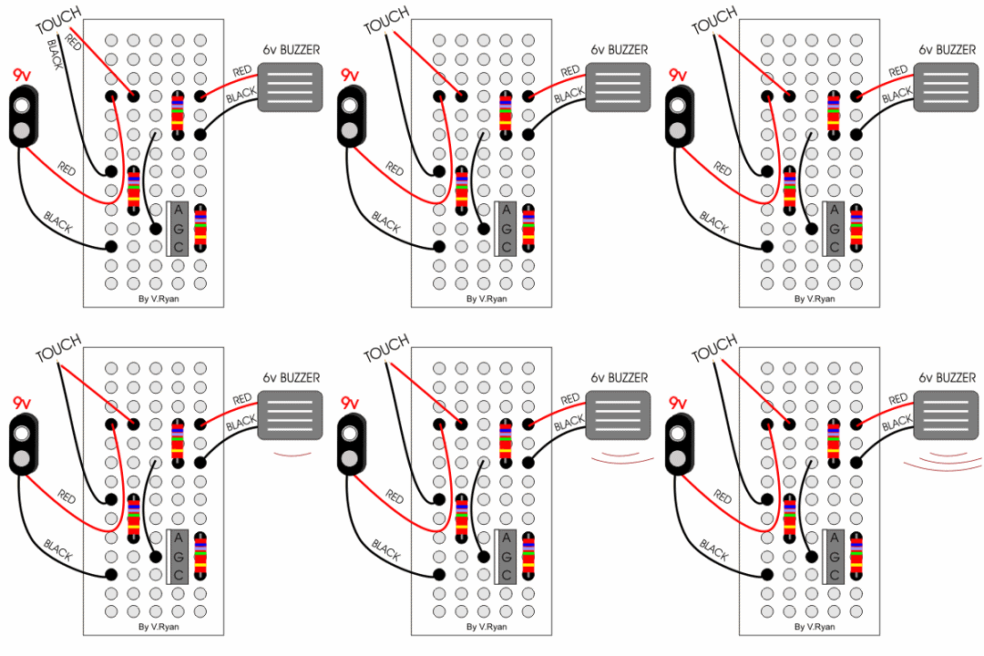
| 5. Construct the thyristor circuit using a breadboard and the components listed below. Be careful to line up the components accurately. The black dots show the position of wires and components. | |
 |
|
|
COMPONENTS Three 1K resistors. |
|
| When the battery is connected power is supplied to the circuit. Touching the red and black wires for a split second activates the thyristor which allows the buzzer to sound. The buzzer will continue to sound even though the red and black wires are not touching. The ‘buzzing’ can only be stopped if the battery is removed. | |
| CLICK HERE FOR ELECTRONICS INDEX PAGE | |
|
|
|
