| CLICK HERE FOR INDEX PAGE | |
| THE DARLINGTON PAIR | |
| V. Ryan © 2002 - 2022 | |
| PDF FILE - CLICK HERE FOR PRINTABLE WORKSHEET BASED ON EXERCISE BELOW | |
| CLICK HERE FOR POWERPOINT VERSION OF WORKSHEET | |
|
Transistors are an essential component in a sensor
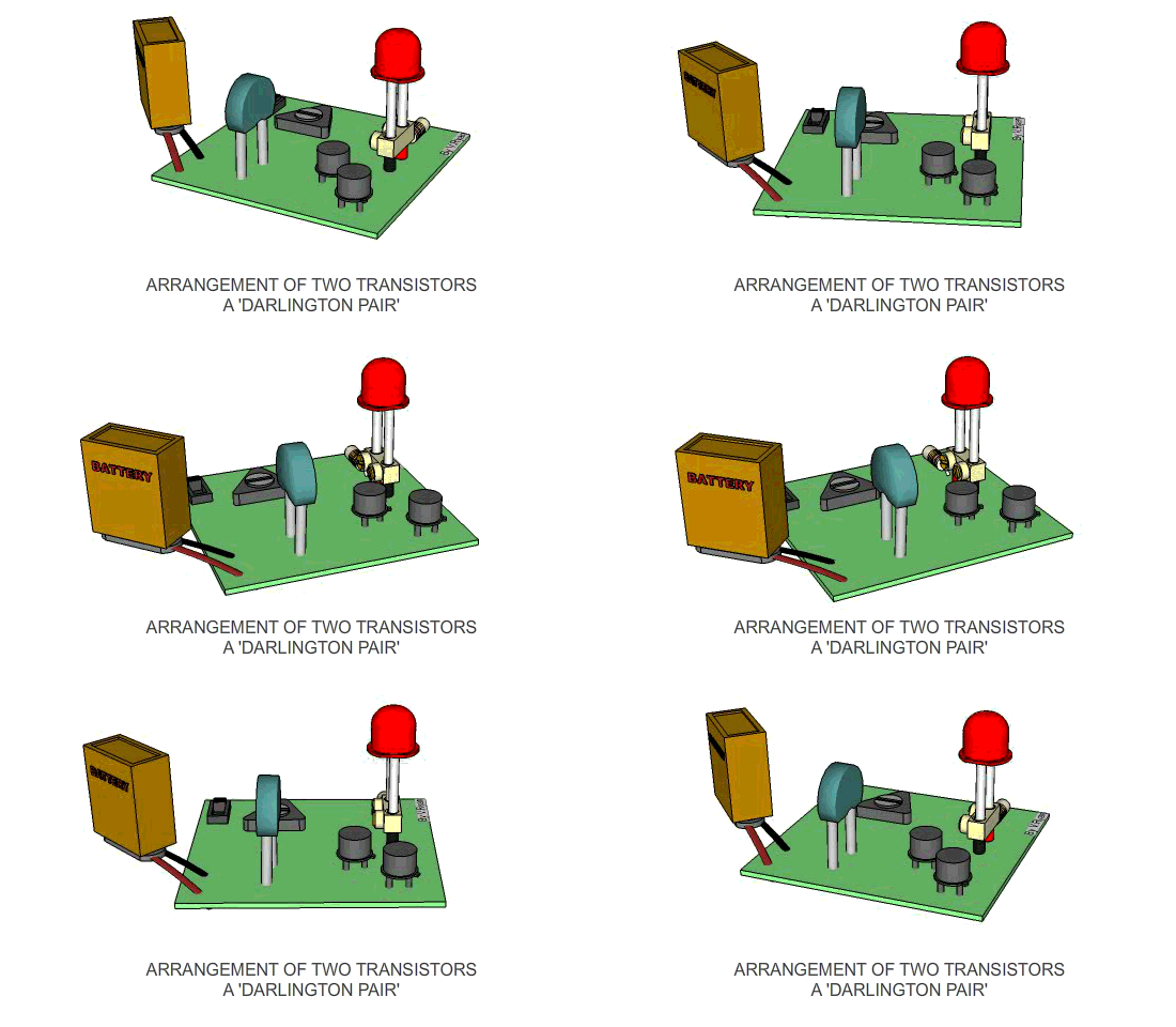
circuit. Usually transistors are arranged as a pair, known as a ‘DARLINGTON
PAIR’. It is very important that you can identify this
arrangement of transistors and state clearly why they are used. |
|
|
The circuit below is a temperature sensor. When the temperature drops below zero the LED lights. This type of system is often seen in a car and warns the driver of the possibility of icy conditions. The two transistors are known as a darlington pair. Without a darlington pair the circuit would probably fail. The two transistors amplify the weak current in the circuit allowing the LED to light. |
|
 |
|
|
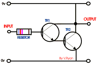
The circuit opposite is a ‘Darlington Pair’ driver.
The first transistor’s emitter feeds into the second transistor’s base
and as a result the input signal is amplified by the time it reaches the
output. |
|
|
|
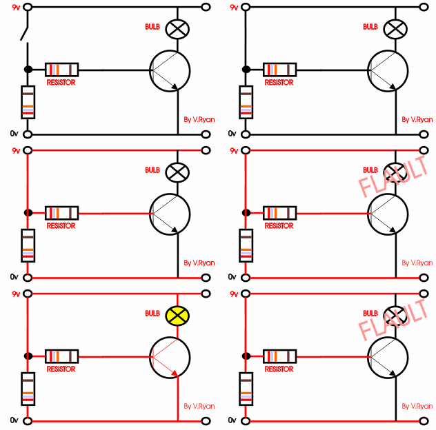
The circuit to the right shows a single transistor.
When the switch is pressed current flows from the 9v to the 0v and also
to the base of the transistor. This allows the transistor to switch and
in turn, current / voltage flows through the bulb, which lights. |
|
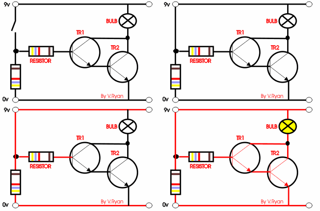
A possible solution is seen to the right. A second
transistor is added to the circuit, the circuit is now likely to work as
the original signal / current is amplified. |
|
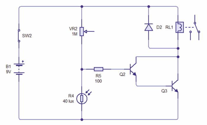
| CIRCUIT WIZARD SOFTWARE SIMULATION OF LIGHT / DARK SENSOR SHOWN ABOVE | |
 |
|
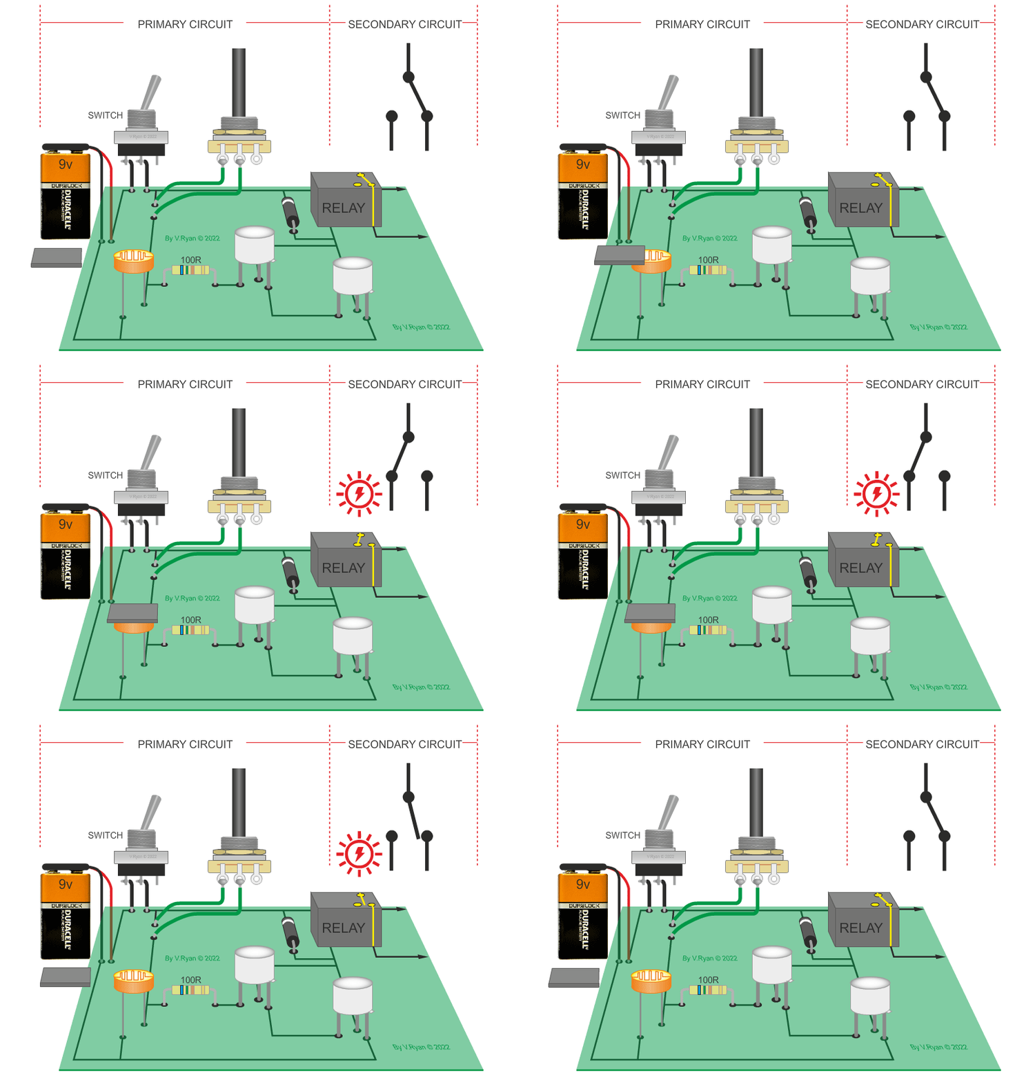
| PICTORIAL REPRESENTATION OF THE LIGHT / DARK SENSOR | |
| The circuit below is a light / dark light sensing circuit. When the light level drops (the LED is covered) the relay energises the relay, allowing a secondary circuit to work. |
|
 |
|
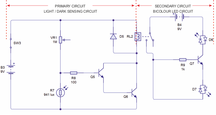
| LOW LIGHT LEVEL WARNING CIRCUIT | |
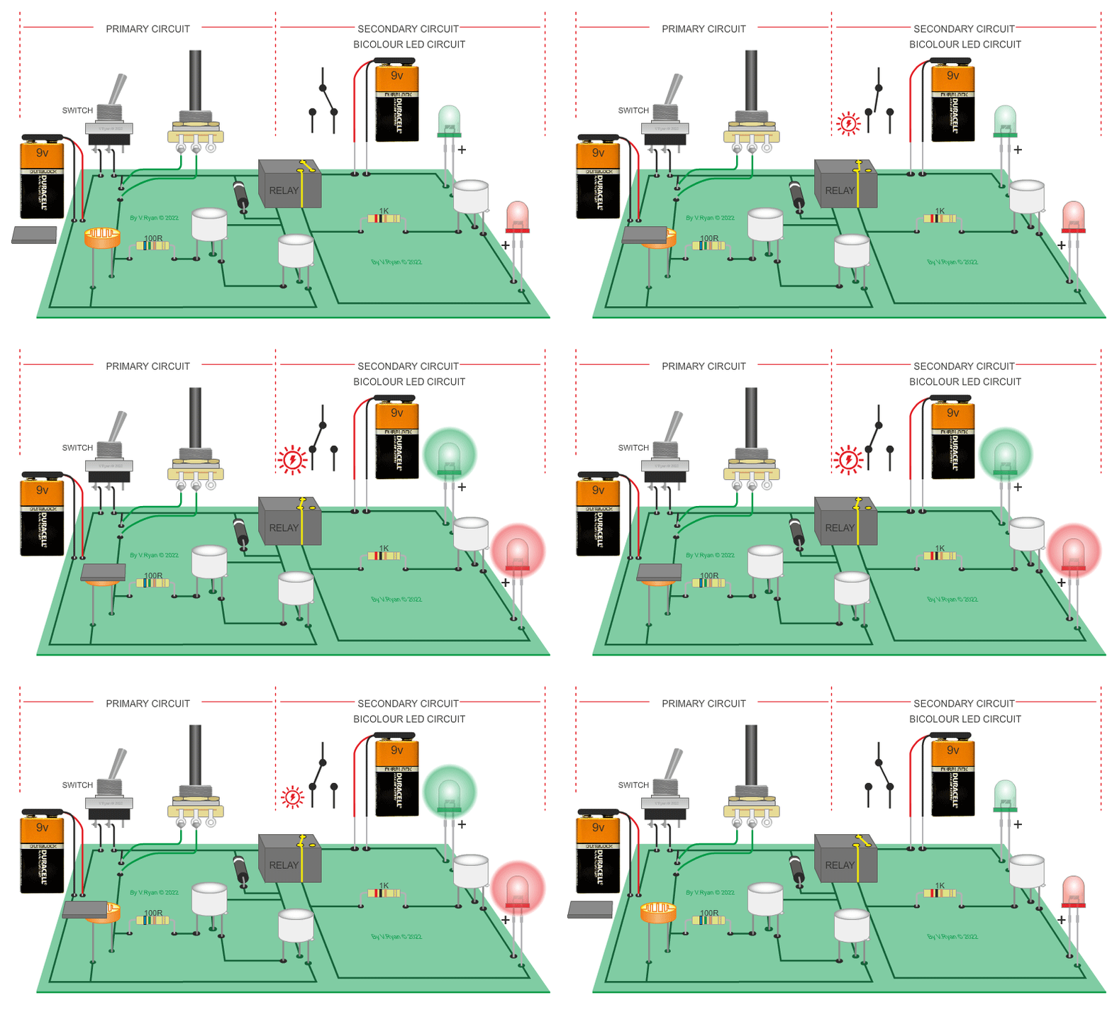
| The circuit below is composed of a light / dark sensing circuit (the primary circuit) and a warning light circuit (the secondary circuit). When the light level drops (the LED is covered) the relay energises, switching on the secondary circuit, illuminating the LEDs. Bicolour LEDs have been used. The variable resistor increases or decreases the sensitivity of the circuit. The darlington pair triggers the relay. |
|
 |
|
| PICTORIAL REPRESENTATION OF THE LOW LEVEL LIGHT CIRCUIT | |
 |
|
| MODULAR CIRCUITS (PREBUILT CIRCUITS THAT 'CLIP' TOGETHER) | |
| Below is a system designed to monitor the temperature of a car radiator. When the radiator temperature becomes too high the voltage from the temperature sensor and sensor unit changes. The comparator detects this change in voltage and activates the darlington pair. The darlington pair driver provides enough amplified current for the motor to operate, cooling the car radiator. . | |
|
|
|
| If the darlington pair is replaced with a transistor module (composed of one transistor) - what would you expect to happen? | |
|
|
|
| The single transistor does not amplify the current to the motor. As a result the motor does not ‘spin’. Control Studio software allows experimentation, without the need to build a real circuit using actual components. It saves time and money as components are not wasted. | |
|
|
|
