Diodes allow electricity to flow in only one direction, but a diode will only conduct electricity, when the supply reaches its threshold. The threshold for common silicon diodes is 0.6 volts. This can be clearly seen in the voltage dropper circuit, below.
As the threshold is 0.6volts, for each diode, the voltage drops by the same amount. This property can be very useful, if the source voltage is higher than the required output voltage.
The circuit below shows a number of digital multimeters, each connected after a diode. After each diode, the voltage can be seen to drop by 0.6 volts. In this way, diodes can be used to reduce voltage, in a circuit.
ZENER DIODES
Zener diodes allow electricity to flow through them, in the same way as normal diodes. However, a Zener Diode is different, in that it will allow electricity to flow in the opposite direction (reverse), when the voltage exceeds its ‘threshold’ value. This is known as the ‘breakdown voltage’ OR ‘zener voltage’. The zener diode can be used as a type of switch, within a circuit.
The circuit below shows the operation of a zener diode. The LED circuit on the left, does not include a zener diode. As the voltage increases, the LED illuminates as normal, under 3 volts.
However, the circuit on the right includes a zener diode. The diode is arranged to prevent the flow of electricity, until the voltage reaches the breakdown voltage / zener voltage of the diode. Then, it acts as a ‘switch’, allowing electricity to flow through it, illuminating the LED.
The circuit below has five LEDs and zener diodes. The LEDs illuminate in sequence, due to the different values of the resistors. As each zener diode reaches its breakdown voltage / zener voltage, it allows electricity to flow through it, illuminating the LED.
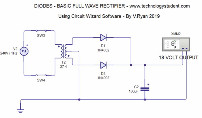
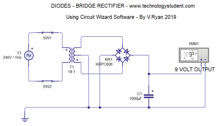
RECTIFYING CIRCUITS
A Full Wave Rectifying Circuit, is one that converts an AC (Alternating Current) input voltage, mains electricity, to a DC (Direct Current) voltage. AC electricity can be transmitted over long distances, from power stations. When Alternating Current is converted to Direct Current, the process is called Rectification. AC is a current that reserves direction of flow at regular intervals. The rectification process, ensures that the output Direct Current flows in one direction only and makes it suitable for many of the electronics devices we use in our homes and with mobile devices. The two rectifying circuits shown below, clearly show the important role played by diodes.