| CLICK HERE FOR INDEX PAGE |
| |
| FIELD-EFFECT TRANSISTORS - FETS |
| V.Ryan © 2019-2022 |
| |
| PDF FILE - CLICK HERE FOR PRINTABLE WORKSHEET |
| |
 |
| |
| |
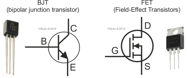
FETs have a source, drain and gate, which are arranged in a similar way, to the ‘pins’ of a bipolar junction transistor (BJTs), such as an NPN or PNP transistor - collector, base and emitter. The gate of a FET, plays a similar role as the base of a BJT. When the gate is triggered, it allows current to flow through the drain and source. However, it requires vary little current to trigger the gate, unlike BJTs. |
| |
 |
| |
FETs are digital devices, acting as a ‘switch’ or as an ‘amplifier’. They have a relatively high input resistance, which is an advantage over BJTs. FETS have the advantage, that they are voltage controlled devices, whereas BJTs, such as NPN transistors are current controlled, drawing more current from a circuit.
FETs offer more protection to a secondary circuit. Consequently, they are ideal for providing an output for solenoids and motors, ensuring that they work properly. FETs are physically smaller than BJTs. Therefore, a finished commercial circuit, will have a smaller footprint, than one incorporating BJTs.
Although FETs are more expensive to manufacture than BJTs, they are preferred in most commercial circuits, with the exception of amplifier circuits. Bipolar junction transistors are preferred for amplifier circuits, as they produce more GAIN than FETs. |
| |
| CLASSIFICATION OF COMMON FETs |
| |
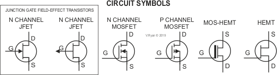
A variety of FETs are available - some are shown below.
JFET-Junction Field Effect Transistor
MESFET-Metal Semiconductor Field Effect Transistor
HEMT-High Electron Mobility Transistor
MOSFET-Metal Oxide Semiconductor Field Effect Transistor |
| |
|
|
| |
 |
| |
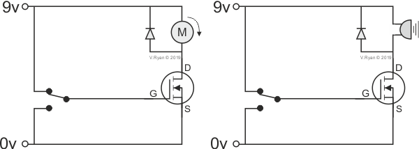
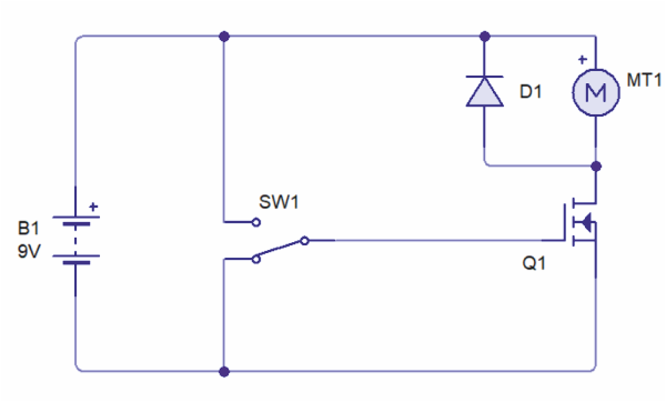
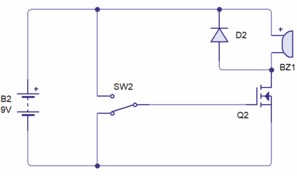
| The two circuits below include a N channel MOSFET. An input to the Gate, triggers the MOSFET, allowing current to flow through the Drain and Source, driving the motor the and buzzer. |
| |
 |
| |
| CIRCUIT WIZARD VERSION OF FET / MOTOR CITCUIT |
| |
 |
| |
|
|
| |
| PICTORIAL REPRESENTATION OF FET / MOTOR CIRCUIT |
| |
 |
| |
| CIRCUIT WIZARD VERSION OF BUZZER / MOTOR CITCUIT |
| |
 |
| |
| PICTORIAL REPRESENTATION OF FET / MOTOR CIRCUIT |
| |
 |
| |
|
|
| |
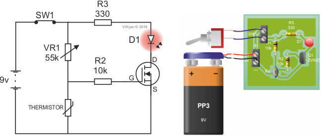
| The temperature sensor circuit below, depends in part on the MOSFET. As the temperature drops, the LED illuminates, as a warning light. The 100K variable resistor has been set at a value of 55K. As the temperature drops to below 3 degrees centigrade, the LED illuminates. Altering the setting of the variable resistor, determines when the LED illuminates. When the Gate is triggered, current flows through the Drain and the Source, allowing the LED to illuminate. |
| |
 |
| |
| CLICK HERE FOR ELECTRONICS INDEX PAGE |
| |
|
| |
|