| CLICK HERE FOR INDEX PAGE | ||
| ELECTRONIC MEMO BOARD - CIRCUIT LAYOUT | ||
| V. Ryan © 2017 | ||
| WHAT THE FLASHING LED CIRCUIT LOOKS LIKE and HOW THE CIRCUIT WORKS | ||
|
The slide switch is ‘switched’ on, allowing electricity to flow through
the entire circuit. It first flows through the flashing LED. The flashing
LED has two states, ON or OFF and it automatically alternates between the
two, controlling the other LEDs. LEDs only need a small amount of voltage / current to light. If one LED was connected to the 9 volt battery, it would be destroyed. One LED has very little resistance. The fact that four LEDs are connected in series together, means that the resistance in the circuit is increased and all four LEDs function normally. |
||
|
FINISHED CIRCUIT |
REAL WORLD VIEW CIRCUIT WIZARD SOFTWARE |
|
| This is a photograph of the manufactured circuit. | This is the flashing LED circuit drawn in Circuit Wizard software. The software allows the circuit to be tested and simulated on screen. | |
 |
 |
|
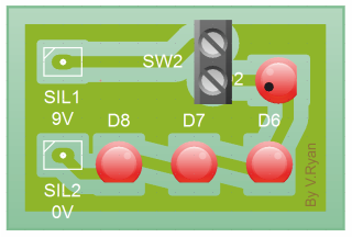
| THREE DIMENSIONAL VERSION OF THE FLASHING LIGHT CIRCUIT | ||
 |
||
| CLICK HERE FOR HTML ANIMATION OF CIRCUIT LAYOUT | ||
|
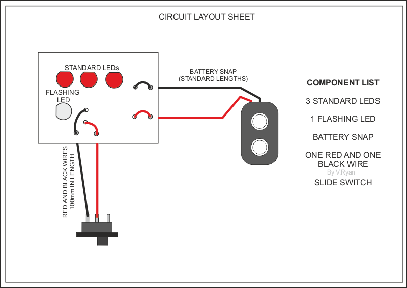
COMPONENTS 3 STANDARD LEDS 1 FLASHING LED BATTERY SNAP ONE RED AND ONE BLACK WIRE SLIDE SWITCH |
||
| CIRCUIT DIAGRAM | ||
| The flashing LED circuit below, clearly shows the layout of the components (note the switch is in the OFF position) | ||
 |
||
| CLICK HERE FOR ANIMATION OF CIRCUIT (SWITCH IN ON POSITION) | ||
| BASIC LAYOUT | ||
| Please note that extra large holes (seen shaded in grey) have been drilled with a 2mm drill bit. The insulation part of the red and black wires fit through these holes. They help to prevent the wires been pulled away from the PCB, when they are soldered in position. | ||
 |
||
| EXERCISE - Draw your version of the Flashing LED Circuit. (see sample below) | ||
 |
||
| CLICK HERE FOR ELECTRONICS INDEX PAGE | ||