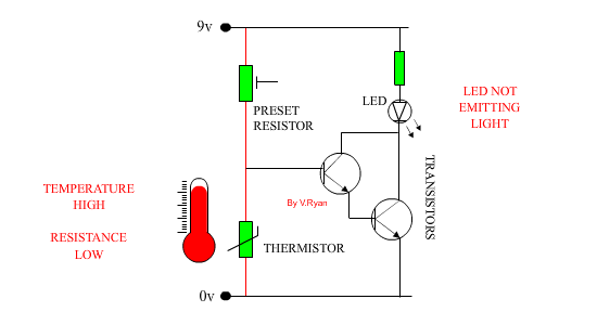
Sensors such as the thermistor based circuit shown
below are not always reliable. This is usually due to the circuit relying
on one transistor. The circuit below has two transistors, called a
‘Darlington Pair’. This arrangement of transistors amplifies current
flowing from the thermistor and ensures that the LED lights.
When the temperature is LOW.
Resistance of thermistor high and current flows through the transistors
allowing the LED to light
High temperature.
Resistance of thermistor reduces significantly and current flows from
positive straight to negative. The LED does not light.
The circuit shon below is an alternative. The darlington pair energises the relay, which allws the illumination of the LED. The diode is arranged in parallel with the relay, to prevent Back EMF, which is curent that flows in the 'worng' direction, which could damage the relay.
QUESTION:
1. The LED in the circuit above lights when the temperature is low (icy).
However, it would be useful if the LED would light when it is warm/hot.
This circuit could be used for a warning device when temperatures are too
high.. Draw an updated version of the circuit that would allow this to
happen.
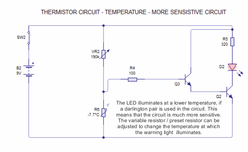
CIRCUIT WIZARD SIMULATION OF MORE SENSISTIVE TEMPERATURE CIRCUIT
(USE OF DARLINGTON PAIRS)
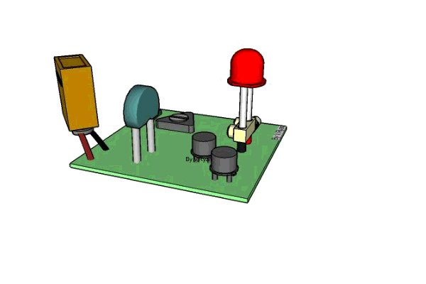
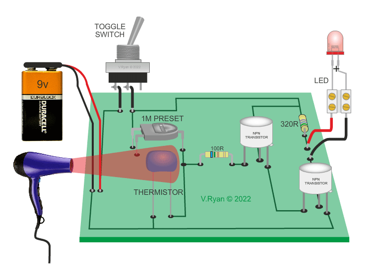
PICTORIAL ILLUSTRATION OF SENSISTIVE TEMPERATURE CIRCUIT