| CLICK HERE FOR INDEX PAGE |
| |
| TRICOLOUR LEDs |
V.Ryan © 2022 |
| |
| PDF FILE - CLICK HERE FOR PRINTABLE WORKSHEET |
| |
| CLICK HERE FOR POWERPOINT VERSION OF WORKSHEET |
| |
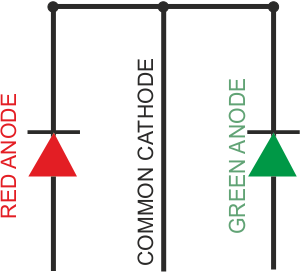
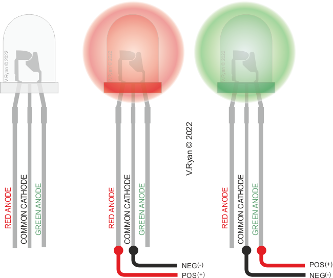
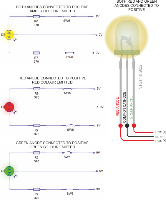
| A typical tricolour LED (shown below) has two anodes, that can be connected to the positive side a circuit. A single cathode is connected to the negative. The LED will either emit green or red light, depending on which anode is connected to positive / which one has current flowing through it. |
| |
 |
| |
 |
| |
|
|
| |
| CIRCUIT WIZARD SOFTWARE SIMULATION |
| |
 |
| |
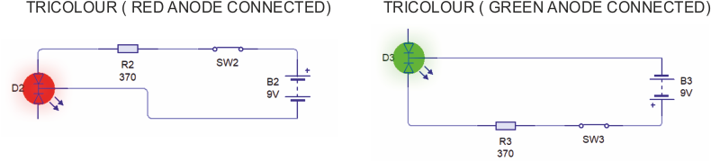
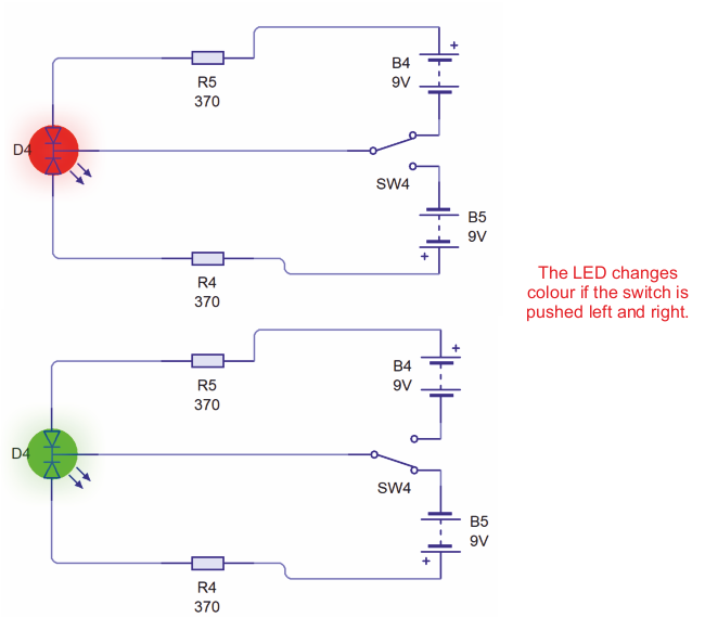
Two circuits are shown in pictorial form below. With the first circuit, when the toggle switch is pushed to the left, the current flows through the red anode and the LED emits red light.
With the second circuit, the toggle switch is pushed to the right, current flows through the green anode and the LED emits green light. |
| |
 |
| |
 |
| |
|
|
| |
| IMPORTANT |
| |
| NOTE: If a positive current is supplied to both the green and red anodes, a third colour is emitted, often regarded as amber. See circuit simulations below. |
| |
| CIRCUIT WIZARD SOFTWARE SIMULATION |
| |
 |
| |
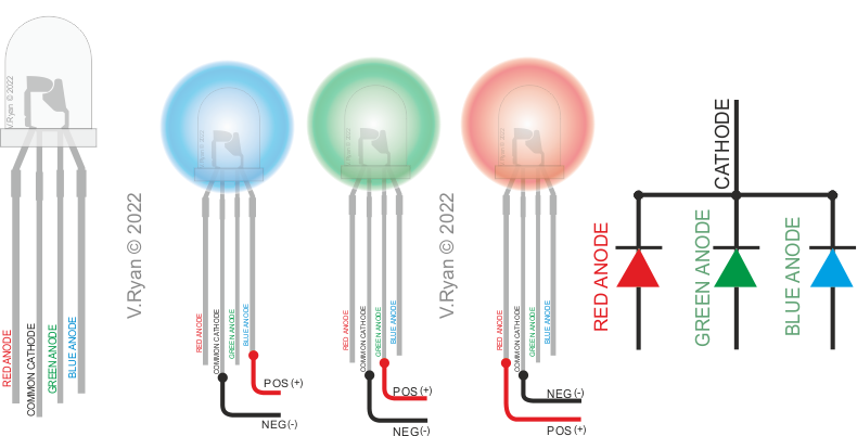
| Tricolour LEDs can also have four leads (three anodes - blue, green and red). The ‘common’ is connected to the negative. |
| |
 |
| |
|
|
| |
| MORE COMPLEX TRICOLOUR LED CIRCUIT |
| |
| Both anodes of the tricolour LED (shown below) are connected to the circuit. The circuit diagrams shows how the switch determines, which of the anodes is connect to ‘positive’. This determines the colour emitted (green or red). The switch type in this simple circuit is a Single Pole, Double Throw (SPDT). |
| |
| CIRCUIT WIZARD SOFTWARE SIMULATION |
| |
 |
| |
| PICTRIAL REPRESENTATION OF THE CIRCUIT |
| |
 |
| |
| |
| |
| CLICK HERE FOR DESIGNER INDEX PAGE |
| |
|
| |
|