| CLICK HERE FOR INDEX PAGE | |
| COMPOUND GEARS | |
| V. Ryan © 2001 - 2024 | |
| PDF FILE - CLICK HERE FOR PRINTABLE WORKSHEET | |
|
A compound gear is a number of gears fixed together. Consequently, they
rotate at the same speed. An example can be seen below. The gears that make up a compound gear usually differ in size and have a different number of teeth. This is useful if there is a need to speed up or slow down the final output. For the example seen below, the output speed will be faster than the input speed. |
|
 |
|
| GEAR SYSTEM (INCLUDING COMPUND GEARS) - CENTRE LATHE HEADSTOCK | |
| Compound gears are multiple gears ‘stacked’ together, to achieve different gear ratios. They are used to transmit power and motion between different shafts. A good example is the gear system inside the headstock of a centre lathe | |
 |
|
| TYPICAL SIMPLIFIED EXAMPLE OF A COMPOUND GEAR | |
 |
|
| Another example of a compound gear system is seen below. Gears C and B are fixed together and rotate in the same direction and at the same speed. | |
 |
|
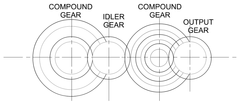
| The gear train below has an arrangement of gear wheels including two compound gears. Gear trains like this are often found inside machines such as centre lathes and milling machines. On a smaller scale, plastic gear trains are found inside DVD recorders. They ensure that the DVD disk spins at exactly the right speed (RPM Revolutions Per Minute). | |
 |
|
| When drawing a gear train it is not necessary to draw all the individual teeth. Two concentric circles represent the gear wheel and teeth. The diagram below shows how the teeth mesh together. | |
 |
|
| THE CENTRE LATHE | |
 |
The headstock of a centre lathe contains a complex gear train and many of the individual gears are compound gears. This arrange allows the speed of the lathe to be adjusted so that the chuck of the lathe rotates at the correct speed for the metal being turned/machined. |
 |
|
| However, sometimes the only way to set the lathe to a particular speed is to change the gear arrangement inside the headstock. Most machines will have a number of alterative gear wheels for this purpose. | |
|
|
|