| CLICK HERE FOR INDEX PAGE | |
| PULLEY SYSTEMS - 1 | |
| V. Ryan © 2017-2024 | |
| PDF FILE - CLICK HERE FOR PRINTABLE WORKSHEET | |
|
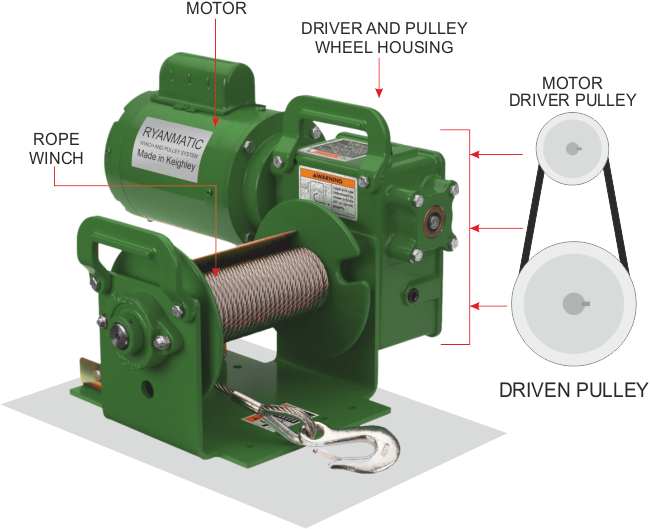
Pulley systems are used when there is a need to transmit rotary motion. The diagram below shows a simple system comprised of two pulley wheels and a belt. It is a simple mechanical device to winch up and down a rope. When the motor is turned on it revolves the driver pulley wheel. The belt causes the driven pulley wheel to rotate as well, winding out the rope. The small pulley is known as the DRIVER, because it is connected to the motor which provides all the power / drive to the entire pulley system. The larger pulley (DRIVEN pulley) is 'driven' round by the driver pulley wheel. It rotates because of the power provided by the driver pulley wheel. |
|
|
|
|
| REAL WORLD PRACTICAL APPLICATION | |
 |
|
|
|
Pulley wheels are grooved so that the belt cannot slip off. Also, the belt is pulled tight between the two pulley wheels (in tension). The friction caused by this means that when the driver rotates the driven follows. Without friction, without the belt being pulled tight and in tension, the belt would slip and the pulley system would fail. |
|
|
|
|
Most pulley wheels have a central shaft on which they
rotate. To keep the wheel firmly attached to the shaft it is usual to
use what is called a ‘key’. |
|
|
|
|