| CLICK HERE FOR INDEX PAGE | |||||||||||||||||
| CIRCUIT DIAGRAM TO PCB LAYOUT 1 | |||||||||||||||||
| V. Ryan © 2002 | |||||||||||||||||
|
Usually software such as Crocodile Clips is used to draw a circuit on screen and to test it. Once the circuit works, at least within the software, it has to be converted into a printed circuit board layout before it can be made. To do this the crocodile clips version of the circuit is imported into software such as PCB Wizard. This software converts the circuit diagram automatically to a PCB layout. (PCB = Printed Circuit Board) |
|||||||||||||||||
|
|
|
||||||||||||||||
|
CIRCUIT DIAGRAM OF A SIMPLE LED CIRCUIT |
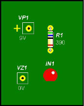
LED CIRCUIT AS A PCB LAYOUT |
||||||||||||||||
|
|
The circuit diagram on the left clearly shows a simple LED circuit. The 9 volt supply, resistor and LED are laid out as they would be if drawn by hand. The drawing on the right is the PCB version of the same LED circuit. This diagram shows the tracks of which represent 'lines' between the components. The drawing below is a view of how the PCB really looks when the components are soldered in position. |
|
|||||||||||||||
|
|
|||||||||||||||||
|
|
|||||||||||||||||
|
A Transistor Circuit |
|||||||||||||||||
|
|||||||||||||||||
| CLICK HERE FOR PCB INDEX PAGE | |||||||||||||||||