|
PIC Microcontrollers can be programmed very easily using PIC-Logicator software. In order to program there is a need to understand the basic functions of a flowchart. The example below sets out the stages involved in writing a simple program which enables the PIC Microcontroller to switch on an LED. |
||||||
|
QUESTION: 1. Design a program/flow chart to turn on an LED after a switch has been pressed. The LED must stay on for five seconds and then switch off. |
||||||
|
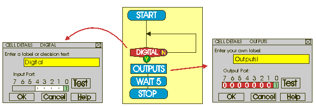
First construct the flow chart shown opposite by dragging the symbols (known as CELLS) across from the command list on the right hand side of the screen. |
||||||
|
|
||||||
|
The DIGITAL cell represents the switch. When you have dragged it into position, click on it twice and a menu appears. Click on input port zero and it changes to 1. This part of the program will always be looking for a switch connected to input 0 to be pressed. When the switch is pressed the flowchart then moves on to the OUTPUTS. |
The OUTPUTS cell controls any output devices connected to the PIC-Microcontroller, such as LEDs. Double click on the OUTPUT cell and a menu will appear. Click on output port 0 and a 1 will appear. This means that when the program reaches this stage an LED connected to output one will light. |
|||||
|
|
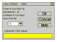
To keep the LED on the WAIT command is used. Double click on the WAIT cell and type in the amount of time, in this case five seconds. |
|||||
|
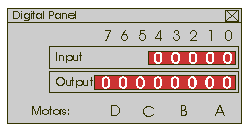
Finish the program with a STOP box, this completes the program. Test your program by using the RUN command. The DIGITAL PANEL will display when inputs are switched and outputs are on. |
|
|||||
|
|
||||||
| QUESTION: | ||||||
|
2a. Produce a flow chart that turns on two LEDs. The first LED must be on for five seconds and then turn off. The second LED must then turn on for ten seconds and turn off. |
||||||
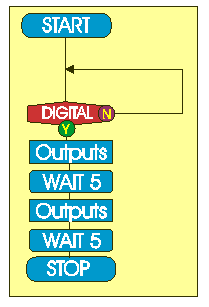
| The flow chart opposite will give
you some idea regarding the flow chart you are to create. 2b. Draw a systems diagram to represent the logicator flow chart you have created. Clearly explain INPUT, PROCESS and OUTPUT |
|
|||||
|
||||||
| QUESTION: | ||||||
|
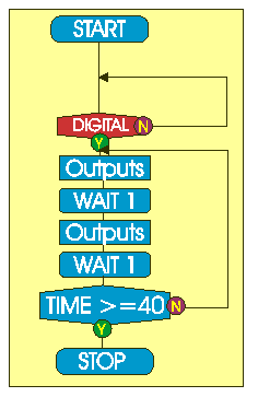
3a. Produce a flow chart that flashes two LEDs alternately for forty seconds, when a switch is pressed. |
||||||
|
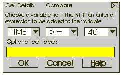
The COMPARE cell could be used. Look at the formula that has been entered below.
|
|
|||||
| 3b. Describe how the time command works, as part of the flow chart. | ||||||
|
|
||||||
