CLICK HERE FOR INDEX PAGE

INPUT, PROCESS, OUTPUT - THE PICAXE-08 MICROCONTROLLER

V. Ryan © 2004 - 2010


PDF FILE - CLICK HERE FOR PRINTABLE WORKSHEET

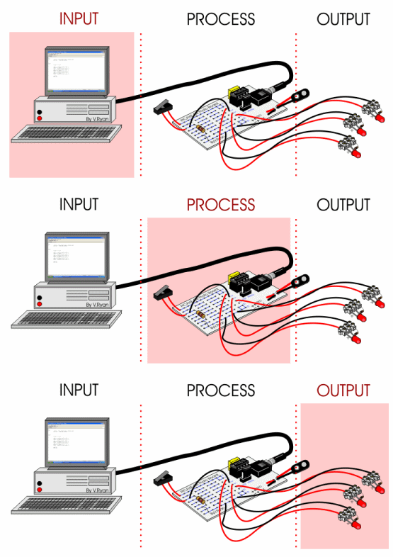
Most control systems can be divided into three stages - INPUT, PROCESS and OUTPUT. The diagram below shows the PICAXE system. The computer is used for programming. Once the programme has been completed, it is downloaded to the PICAXE circuit using a serial cable which connects to both the circuit and the serial port of the computer. This is the INPUT stage. When the programme has been downloaded successfully the serial cable can be unplugged.

The circuit is autonomous (it will work independently) as long as it has a power source. The power source is normally 4.5 volts. If the micro-switch shown on the example PICAXE circuit below is pressed, the circuit begins to follow the instructions programmed into the PICAXE Integrated circuit. This is the PROCESSING stage.

The programme flashes the LEDs on and off. This is the OUTPUT stage. This simple circuit can be altered so that motors are switched on and off or sound is generated as well as other outputs.


THE SYSTEMS DIAGRAM

Computer - used to write a programme. The programme can be tested on screen so that obvious faults can be corrected.


PICAXE circuit - once the programme is loaded into its integrated circuit, the programme is processed.


LEDs -these are the output for this simple circuit. These flash on and off.
Motors and sound are other output devices.


QUESTIONS:
1. Draw a simplified version of the Systems Diagram representing the PICAXE system.
2. List input devices that can be connected to the PICAXE microcontroller circuit.
3. List output devices that can be connected to the PICAXE microcontroller circuit.


CLICK HERE FOR PIC-MICROCONTROLLER INDEX PAGE


Google
 
Web www.technologystudent.com