| |
| CLICK HERE FOR INDEX PAGE |
| |
| SYSTEMS PREPARATION QUESTIONS 2008 - 10 |
| |
| V. Ryan © 2008-2017 |
| |
| PDF FILE - CLICK HERE FOR PRINTABLE WORKSHEET |
| |
The animatronic clown is controlled by a PIC
Microcontroller. Although it has eight outputs although only six are in
use. Outputs 0, 1 and 2 control the LEDs positioned in the clowns hat.
Outputs 3, 4, and 5 control the arms and bow tie.
When the outputs are on this is represented as LOGIC STATE 1. When the
outputs are off this is represented by LOGIC STATE 0. |
| |
 |
| |
|
|
| |
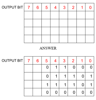
The PIC microcontroller is
programmed so that when it is turned on it goes through a simple routine:
Both arms rise,
the red and green LEDs turn on,
the bow tie then starts to revolve,
all out puts switch off. |
| |
| Complete the table below to show
the output bit pattern when the microprocessor circuit is first turned on. |
| |
 |
| |
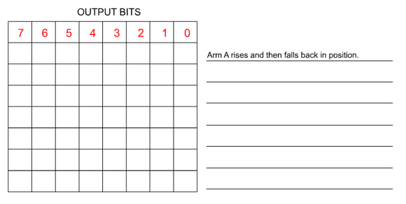
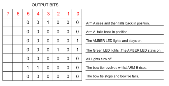
The theme park owner wants the
animatronic clown to follow the sequence outlined below.
Arm A rises and then falls back in position.
The RED LED lights and stays on.
The AMBER LED lights and stays on.
The Green LED lights and stays on.
All Lights turn off.
The bow tie revolves whilst ARM B rises.
The bow tie stops and arm B falls. |
| |
 |
| |
|
|
| |
| Complete the table below to show the output bit pattern
when the sequence stated above is carried out. Alongside each output bit,
write the command that is taking place. The first stage is already written
in position. |
| |
 |
| |
| ANSWER |
| |
 |
| |
| CLICK HERE FOR ELECTRONICS INDEX PAGE |
| |